
TM 5-2420-230-24-2
Turbocharger (010-033)
B3.9 and B5.9 Series Engines
Page 10-34
Section 10 - Air Intake System - Group 10
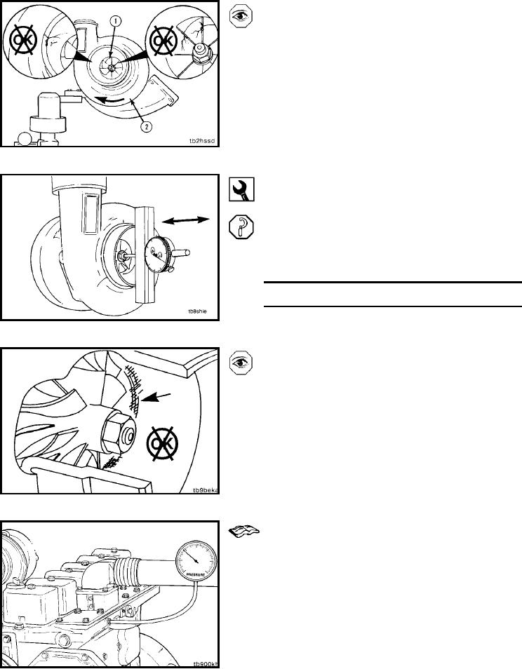
Inspect the housing for damage.
Inspect the turbine wheel and compressor impeller (1) for
fretting or for cracked or broken vanes.
Turn the impeller in the direction shown with the arrow (2)
to inspect the turbine shaft for freedom of rotation. The
shaft must rotate freely.
Replace damaged parts.
Dial Depth Gauge, Part No. ST537
Measure the turbocharger shaft end clearance with the dial
depth gauge, Part No. ST537.
Push the rotor assembly away from the gauge.
Set the gauge on zero.
Push the rotor assembly toward the gauge and record the
data.
End Play
mm
in
0.03
MIN
0.001
0.08
MAX
0.003
Failure of the internal components of the turbocharger can
reduce its effectiveness and also cause excessive smoke
and low power. A bearing failure can produce friction, which
will slow the speed of the rotor assembly. Failed bearings
can also allow the blades of the rotor assembly to rub the
housings, thus reducing the rotor assembly speed.
Malfunctioning turbocharger wastegate failure or
miscalibration of the turbocharger wastegate can result in
excessively high or low boost pressures. Low boost pres-
sures can cause excessive smoke and low power. High
boost pressures can cause major engine damage.
Measure (010-033-010)
Measure the boost pressure at the intake manifold by using
one of the tapped or plugged intake access holes shown in
the illustration. Refer to the specifications in this section.
NOTE: If the engine has charge-air-cooling, testing must
be done to make certain that the charge-air-cooler system
is not leaking or restricting the turbocharger boost pres-
sure. Refer to Procedure 010-027 for charge-air-cooler
testing.
L-1158