
TM 5-2420-230-24-2
Alternator (013-001)
B3.9 and B5.9 Series Engines
Page 13-16
Section 13 - Electrical Equipment - Group 13
16 mm
Remove the alternator mounting capscrew.
Test (013-001-012)
WARNING
Batteries can emit explosive gases. To avoid personal
injury, always ventilate the compartment before servic-
ing the batteries. To avoid arcing, remove the negative
(-) battery cable first and attach the negative (-) battery
cable last.
WARNING
Acid is extremely dangerous and can damage the ma-
chinery and can also cause serious burns. Always pro-
vide a tank of strong soda water as a neutralizing agent
when servicing the batteries. Wear goggles and pro-
tective clothing to avoid serious bodily injury.
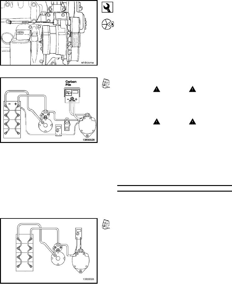
Attach the carbon pile and clip-on ammeter as shown.
Adjust the load from the carbon pile tester to the rated
performance of the alternator.
Measure the voltage drop in both the positive and negative
circuits. Add these together, and compare the sum to the
table.
System Voltage
Maximum Voltage Drop
12 VDC
0.5 VDC
24 VDC
1.0 VDC
Repair or replace the wiring as required to meet the above
specifications.
Alternator Voltage Output Check
Digital Multimeter, Part No. 3377161
Attach the multimeter to the alternator as shown in the
illustration.
With the batteries in a fully charged condition and all the
accessories off, start the engine, and run it at high idle.
Allow time for the voltage to stabilize before taking any
readings.
L-1274