
TM 5-2420-230-24-2
B3.9 and B5.9 Series Engines
Alternator (013-001)
Section 13 - Electrical Equipment - Group 13
Page 13-17
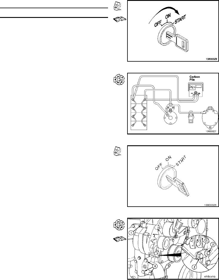
Measure the alternator output voltage.
System Voltage
Maximum Output Volt-
age Limit
12 VDC
15.5 VDC
24 VDC
31 VDC
Repair or replace the alternator or regulator if the voltage
limit exceeds the value in the table.
Refer to the OEM specifications for minimum voltage output.
Alternator Current Output Test
Attach the carbon pile tester and clamp-on ammeter as
shown in illustration.
Start the engine, and operate at high idle.
Adjust the carbon pile load to the rated current output of the
alternator.
If the alternator output current is not within 10 percent of
the rated output, repair or replace the alternator.
NOTE: The alternator output is directly related to the speed
the alternator is turning. A slipping alternator drive belt can
result in an incorrect output reading.
Install (013-001-026)
To assemble the alternator, the alternator mounting com-
ponents must be tightened in the following sequence:
1. Alternator-to-alternator-bracket capscrew
2. Lower brace-to-alternator capscrew
3. Lower alternator-brace-to-water-pump capscrew
4. Water-inlet-to-block capscrews.
NOTE: Wrench size and torque value are determined by
the make and model of alternator. Refer to the Engine
Component Torque Values in the specification section.
L-1275