
TM 5-2420-232-10
0004
QUICK-RELEASE COUPLINGS CONTINUED
Connecting Quick-Release Couplings
0004
1.
Stop the engine (WP 0005).
2.
Remove any residual hydraulic pressure trapped in the service line hose by operating the control levers several times in
both directions.
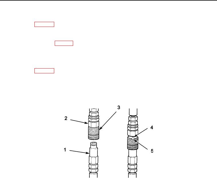
3.
Wipe the two faces (Item 18, WP 0033) of the male (Figure 99, Item 1) and female (Figure 99, Item 2) couplings and
ensure they are clean.
4.
Fit the male couplings into the female couplings. Ensure the sleeve on the female coupling snaps into place.
Disconnecting Quick-Release Couplings
0004
1.
Stop the engine (WP 0005).
2.
Remove any residual hydraulic pressure trapped in the service line hose by operating the control levers several times in
both directions.
3.
Rotate sleeve (Figure 99, Item 3) until sleeve lock pin (Figure 99, Item 4) aligns with the cut out (Figure 99, Item 5). Pull
back sleeve to release the coupling.
435-A0318
Figure 99. Quick-Release Couplings
04
Change 1
0004-102