
TM 5-2420-232-10
0006
COLD START PROCEDURES FOR +32 TO -26F (0 TO -32C)
AND -26 TO -40F (-32 TO -40C) -- CONTINUED
Start Procedure +32 to -26F (0 to -32C) - Continued
0006
2.
Turn the battery disconnect switch (WP 0004) to the ON position.
435-A0320-1
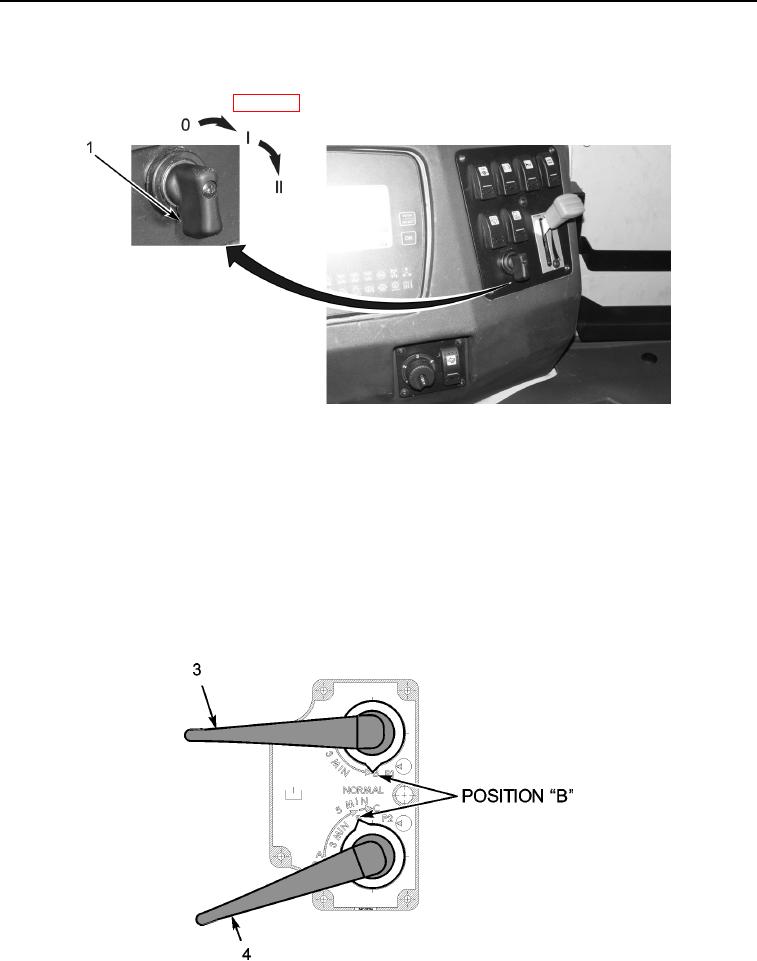
Figure 3. Starter Switch
06
3.
Turn the starter switch (Figure 3, Item 1) to the first position and wait for the grid heater light to extinguish.
4.
Commence cranking for up to 30 seconds unless the engine speed drops noticeably, in which case stop cranking and key
off. Turn the ignition key to the first position and wait for the grid heater light to extinguish. Then continue cranking for
up to 30 seconds unless the engine starts.
5.
Once the engine has started allow it to idle for 2 minutes.
CAUTION
Failure to follow the following step will lead to over-pressurizing the hydraulic cooler.
6.
Slowly close cold start valve number 1 (Figure 4, Item 3) to position B, then slowly close cold start valve number 2 (Fig-
ure 4, Item 4) to position B.
435-A0331
Figure 4. Cold Start Valves - Position B
06
0006-7
Change 1