
TM 5-3805-280-10
Operating the Machine
NOTE: DO NOT use manufacturer's line tags or markings
on line ends to identify lines for this conversion
procedure. The conversion must be done on the
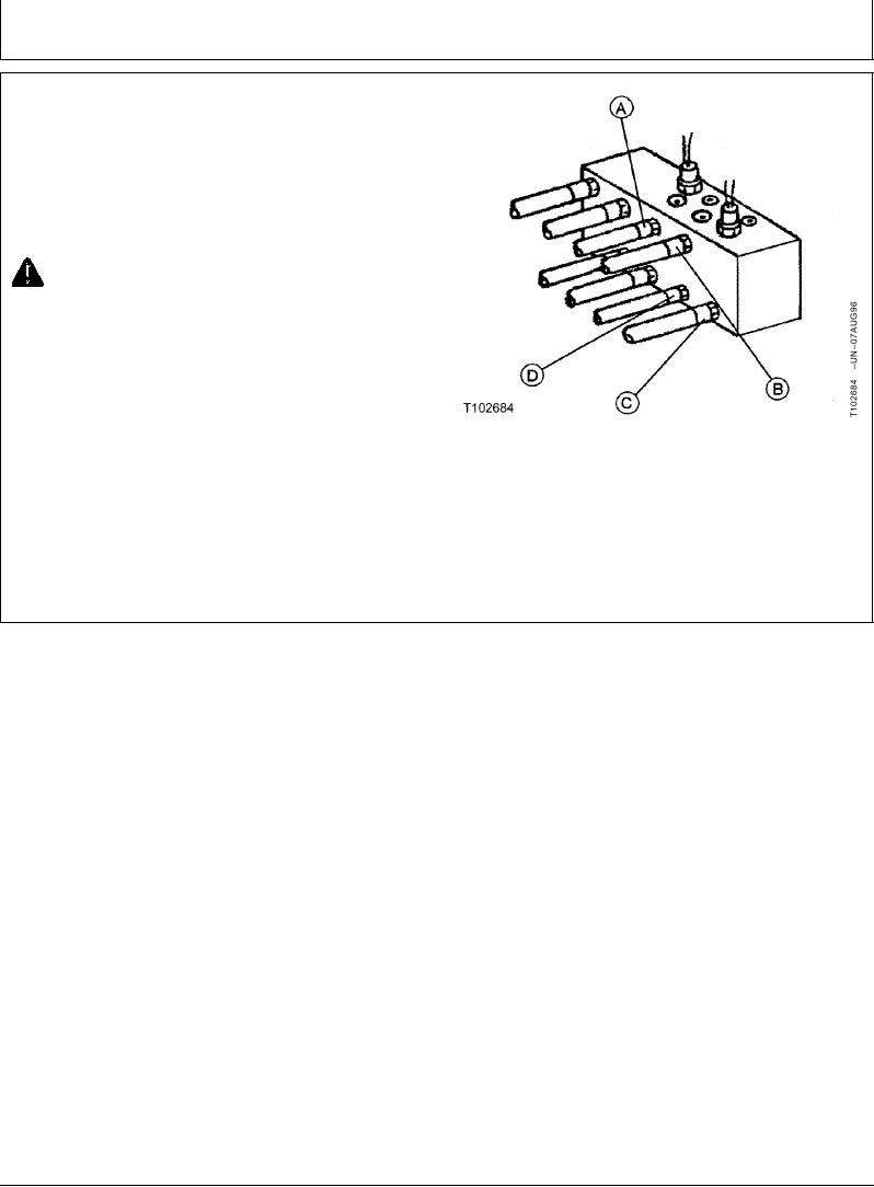
front (cab side) of the flow regulator valve.
Switch hose (A) with hose (C).
Switch hose (B) with hose (D).
CAUTION: Prevent injury from unexpected
control lever function. Install new decals on
control consoles.
8. Install new decals (black on yellow) on control
consoles near the base of control levers. Decals are
enclosed in Operator Manual package. Additional
decals can be purchased from your John Deere dealer.
A--Hose
B--Hose
C--Hose
D--Hose
TX,35,DH5038 1906JUN962/2
7-4