TM 5-3805-280-10
Speed and Pressure Regulation Adjusting Instructions
36518066
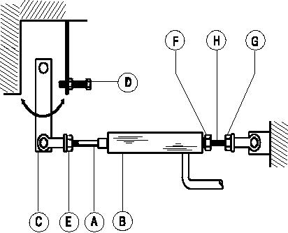
adjustment screw clockwise until throttle air (C)
Normally, regulation requires no adjusting, but if
moves against full speed governor stop (D).
proper adjustment is lost, proceed as follows:
Note: Refer to general data for machine rated
speeds and pressure.
4. Insure that pressure is maintained at rated
pressure, then turn regulator adjustment screw
Before Starting Unit:
counterclockwise until throttle arm (C) just begins
to move.
1. Atop separator tank cover at pressure valve,
loosen locknut counterclockwise. Turn adjustment
Note: Turning regulator adjustment
screw
screw and locknut counterclockwise until no
clockwise will raise pressure at full speed.
tension is felt at the screw. turn screw clockwise
5. Close service valve (engine will slow to idle
one full revolution.
speed). Loosen jam nut (E) on rod (A). Rotate rod
(A) to adjust speed to obtain idle rpm.
After Starting Unit:
6. If necessary, repeat steps 3 and 4.
2. Allow unit to warm up. Then at control panel,
7. At pressure regulator, tighten lock nut.
push "Service Air" Button, if equipped.
8. Limit full load engine speed by loosening jam
nut (F) and (G) and rotating rod (H). When proper
3. Open and adjust service valve (on outside of the
speed is reached, tighten jam nuts.
unit) to obtain the rated operating pressure on the
9. To obtain maximum CFM at any pressure
discharge pressure gauge.
between 80 PSI (550kPa) and the rated operating
pressure, turn adjustment screw of pressure
Note: If the rated operating pressure cannot be
regulator to obtain desired discharge pressure at
full load engine speed. Always lock pressure
maintained with engine at full load speed and rod
setting of adjusting screw.
(A) of air cylinder (B) fully retracted, turn regulator
7-33

