Home
Download PDF
Order CD-ROM
Order in Print
Figure 271. Control Valve (Sheet 2 of 6).
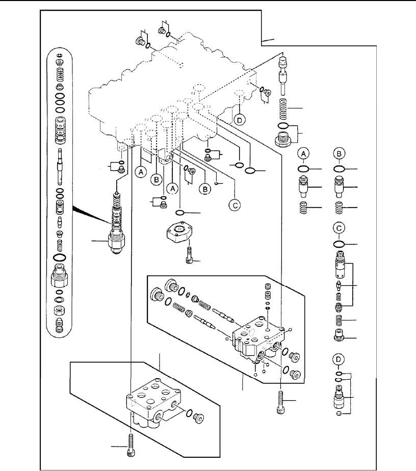
Figure 271. Control Valve (Sheet 4 of 6).
Technical Manual For Hydraulic Excavator Model 230Lcr 1
Page Navigation
744
745
746
747
748
749
750
751
752
753
754
TM
5-3805-280-23P-1
0272
11
28
1
11
21
20
11
17
11
16
16
16
18
22
2
11
11
4
4
29
5
16
15
23
24
25
27
26
19
12
12
Figure
271.
Control Valve
(Sheet
3 of
6).
0272-3