Home
Download PDF
Order CD-ROM
Order in Print
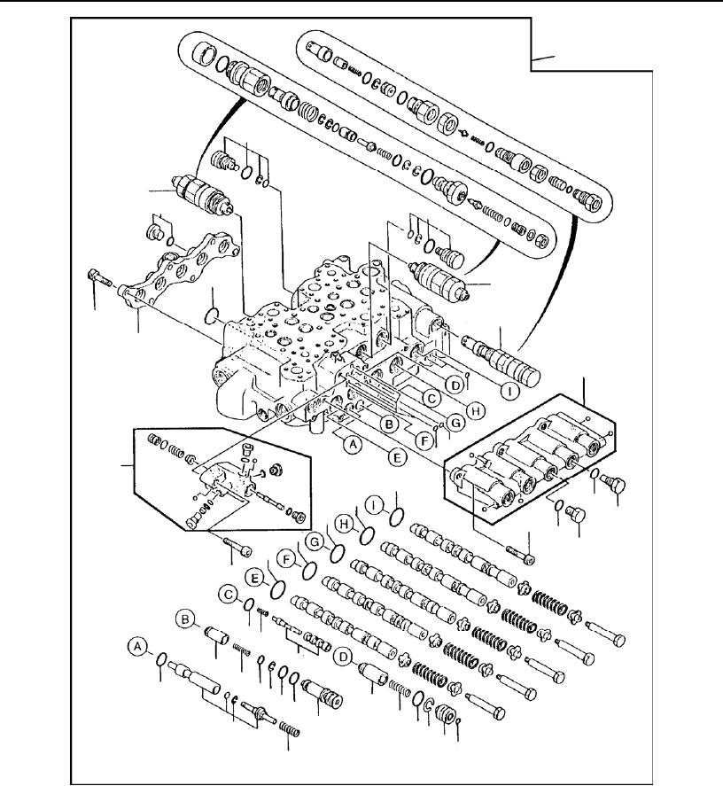
Figure 271. Control Valve (Sheet 3 of 6).
Figure 271. Control Valve (Sheet 5 of 6).
Technical Manual For Hydraulic Excavator Model 230Lcr 1
Page Navigation
745
746
747
748
749
750
751
752
753
754
755
TM
5-3805-280-23P-1
0272
1
42
41
46
42
52
58
47
40
43
44
50
50
18
45
52
52
51
49
52
47
51
52
48
52
12
1734
33
37
38
51
16
57
30
54
55
31
39
5356
35
32
18
36
Figure
271.
Control Valve
(Sheet
4 of
6).
0272-4