
TM 5-3805-280-24-1
Sub-System Diagnostics
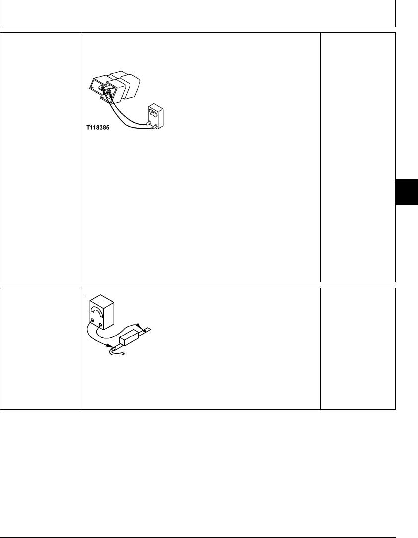
NOTE: A diode can fail in two modes, either shorted or open. Continuity will be
ALTERNATOR SHUT
YES: If continuity is
measured in one direction only in a serviceable diode. Use "diode checking mode" on
DOWN RELAY
measured in both checks,
meter when checking continuity.
ISOLATION DIODE (V2)
diode has failed in a
CHECK
shorted mode. Replace.
NO: If continuity is NOT
measured in either check
diode has failed in an
open mode. Replace.
NO: If continuity is
measured in one check
and not the other, diode
T118385 UN21NOV98
is OK.
Remove diode from connector.
Connect an ohmmeter to diode terminals.
Is continuity measured?
9015
15
Reverse ohmmeter probes.
13
Is continuity measured?
1/1
ALTERNATOR POWER
Disconnect fusible link from battery relay.
YES: Fusible link is OK.
60 AMP FUSIBLE LINK
Check wiring harness.
(F22) CHECK
Connect ohmmeter to both ends of fusible link.
NO: Fusible link has
Is continuity measured?
failed. Replace fusible
link.
T109319 UN28APR97
1/1
4-78