
TM 5-3805-280-24-1
Sub-System Diagnostics
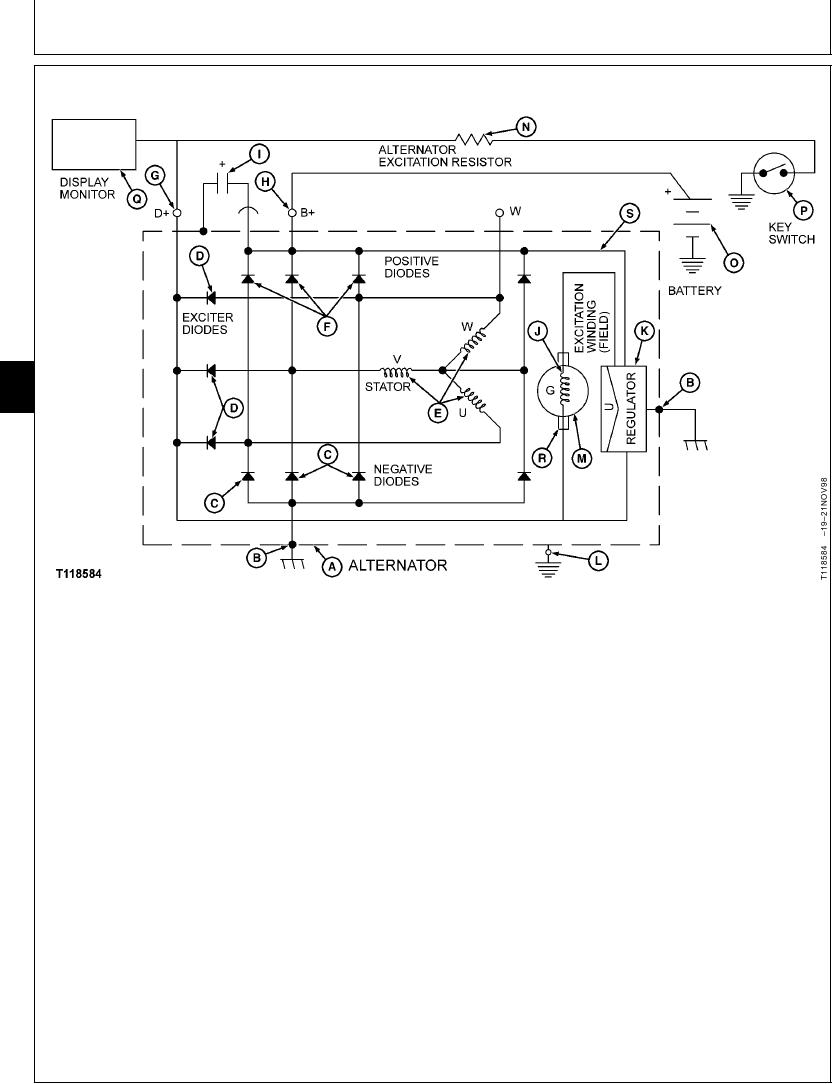
ALTERNATOR THEORY OF OPERATION
9015
15
10
A--Alternator
G--D+ Terminal
L--External Ground
O--Battery
B--Internal Ground
H--B+ Terminal
Terminal
P--Key Switch
C--Negative Diodes
I--Noise Filter
M--Rotor
Q--Display Monitor
J--Excitation Winding
N--Alternator Excitation
R--Brushes
E--Stator Windings
K--Regulator
Resistor
S--Sense Circuit
F--Positive Diodes
resistor to the field coil of the rotor produces a
The alternator has three basic stages for proper
magnetic field which induces current in the
operation. The operating principles are as follows.
three-phase winding of the stator (E). The alternator
reaches cut-in RPM when the induced current is large
PRE-EXCITATION STAGE
enough to produce voltage equal to the battery voltage
plus 1.0 volt. At this time, some current from the stator
When key switch (P) is turned to ON, battery power
is rectified by the exciter diodes (D) (producing battery
flows through the alternator excitation resistor (N) to
voltage at the B+ terminal (G) and is supplied to the
terminal D+ (G) on alternator, excitation winding (J),
carbon brushes and slip rings of the excitation winding,
through regulator (K) and to internal ground (B).
strengthening the magnetic field in the excitation
winding. This in turn will increase the stator voltage.
EXCITATION STAGE
This will occur continuously until the alternator (A) is
fully excited and the alternator regulated voltage is
During alternator start (as the engine speeds up from 0
reached.
to idle) current supplied by the alternator excitation
Continued on next page
CED,OUOE012,13 1927OCT981/2
4-75