
TM 5-3805-280-24-1
Sub-System Diagnostics
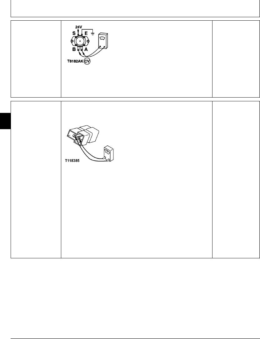
BATTERY RELAY (K14)
Disconnect harness from relay.
YES: Relay is OK. Check
CHECK
wiring harness.
Connect 24 volts to small terminal S and ground small
terminal E.
NO: Relay has failed.
Replace relay.
Does relay click?
Connect ohmmeter to large terminals A and B.
T8182AK
UN03MAR94
Is continuity measured?
1/1
NOTE: A diode can fail in two modes, either shorted or open. Continuity will be
BATTERY RELAY COIL
YES: If continuity is
measured in one direction only in a serviceable diode. Use "diode checking mode" on
SUPPRESSION DIODE
measured in both checks,
9015
meter when checking continuity.
(V11) CHECK
diode has failed in a
15
shorted mode. Replace.
6
NO: If continuity is NOT
measured in either check,
diode has failed in an
open mode. Replace.
NO: If continuity is
measured in one check
and not the other, diode
T118385 UN21NOV98
is OK.
Remove diode from connector.
Connect an ohmmeter to diode terminals.
Is continuity measured?
Reverse ohmmeter probes.
Is continuity measured?
1/1
4-71