
TM 5-3805-280-24-1
Sub-System Diagnostics
YES: Go to next step.
KEY SWITCH (S1)
1--B Terminal
CHECK
2--G1 Terminal
NO: Key switch has failed
3--G2 Terminal
if continuity is not
4--ACC Terminal
measured or continuity is
5--M Terminal
measured between other
6--ST Terminal
terminals. Replace.
Remove harness from key switch.
T8357AK UN09NOV94
Turn key switch to ACC.
Is continuity measured between key switch terminals 1
and 4?
YES: Go to next step.
1--B Terminal
2--G1 Terminal
NO: Key switch has failed
3--G2 Terminal
if continuity is not
4--ACC Terminal
measured or continuity is 9015
5--M Terminal
measured between other 15
6--ST Terminal
5
terminals. Replace.
Remove harness from key switch.
T8357AL
UN09NOV94
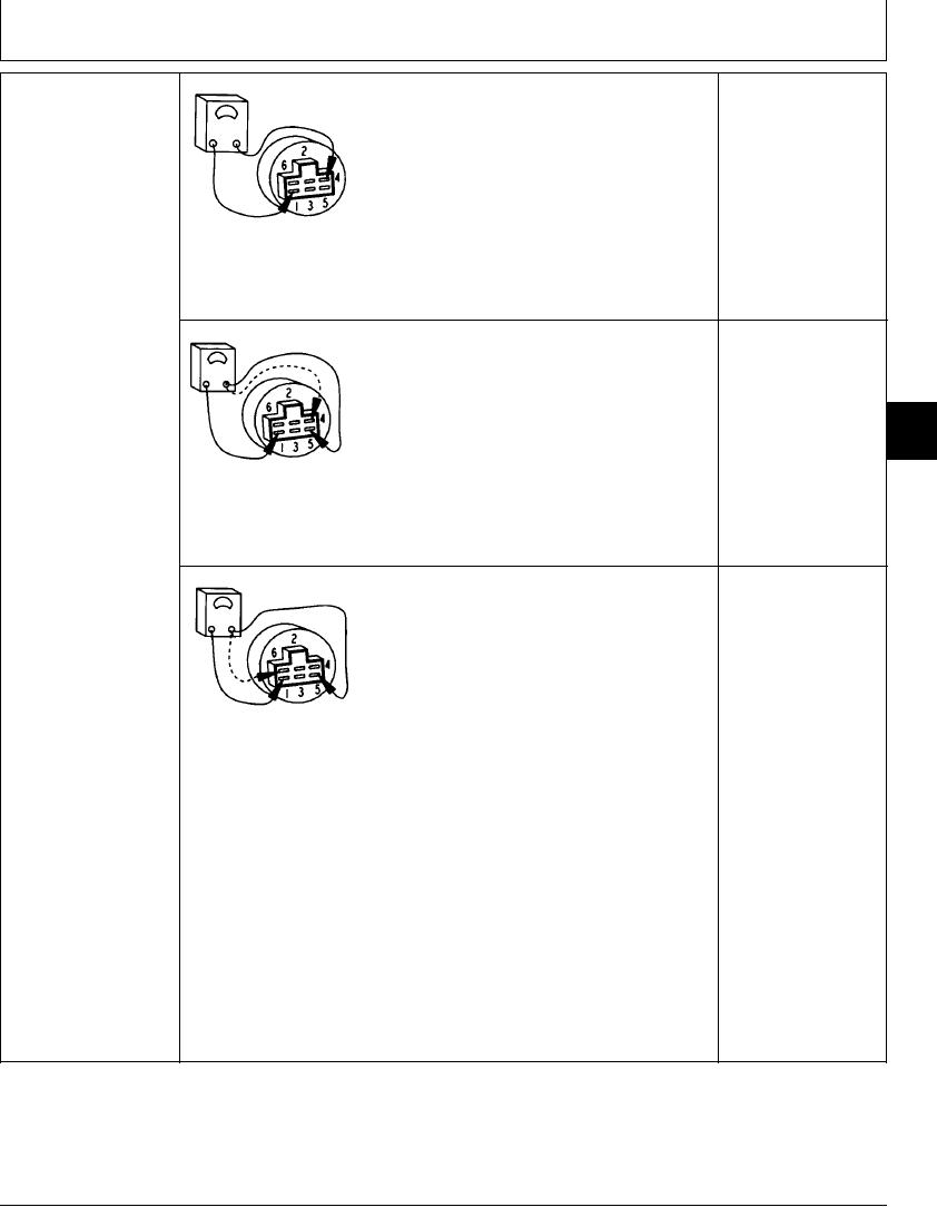
Turn key switch ON.
Is continuity measured between key switch terminals 1
and 4, and terminals 1 and 5?
YES: Key switch is OK.
1--B Terminal
2--G1 Terminal
NO: Key switch has failed
3--G2 Terminal
if continuity is not
4--ACC Terminal
measured or continuity is
5--M Terminal
measured between other
6--ST Terminal
terminals. Replace.
Remove harness from key switch.
T8357AM UN02DEC98
Turn key switch to START.
Is continuity measured between key switch terminals 1
and 5, and terminals 1 and 6?
1/1
4-70