
TM 5-3805-280-24-1
Sub-System Diagnostics
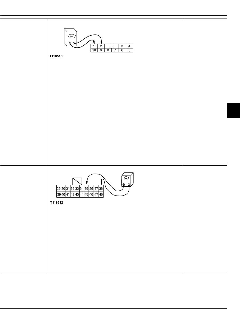
ECONOMY (E) MODE
YES: Switch is OK. Go to
SWITCH (S11) CHECK
next check.
NO: Switch has failed.
Replace.
T118513 UN21NOV98
Turn key switch OFF.
Disconnect engine rpm dial board connector.
Connect ohmmeter between pins 1 and 2 of dial board connector
Measure continuity with economy (E) mode switch in OFF and ON positions.
Does ohmmeter read open with switch in OFF position, and continuity with switch in
9015
ON position?
15
53
Reconnect engine rpm dial board connector.
1/1
ECONOMY (E) MODE
YES: Indicator lamp or
SWITCH (S11) HARNESS
controller has failed.
CHECK
Replace.
NO: Harness has failed.
Repair.
T118512 UN21NOV98
Turn key switch OFF.
Disconnect 20-pin harness connector from monitor controller and display.
Connect ohmmeter between pins 35 and 38 of harness connector
Measure continuity with economy (E) mode switch in OFF and ON positions.
Does ohmmeter read open with switch in OFF position, and continuity with switch in
ON position?
1/1
4-118