
TM 5-3805-280-24-1
Sub-System Diagnostics
With key switch ON and high power mode OFF, push high power (HP) mode switch.
HIGH POWER MODE
YES: Indicator and switch
INDICATOR LIGHT (H5)
are OK.
CHECK
Does switch stay down and high power mode indicator light come ON?
NO: Go to next check.
Push high power (HP) mode switch again.
Does switch return to original position and indicator go OFF?
1/1
HIGH POWER (HP)
YES: Switch is OK. Go to
MODE SWITCH (S12)
next check.
9015
CHECK
15
NO: Switch has failed.
54
Replace.
T118515 UN21NOV98
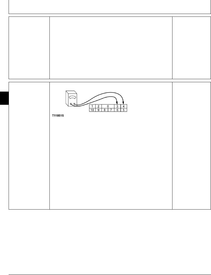
Turn key switch OFF.
Disconnect engine rpm dial board connector.
Connect ohmmeter between pins 3 and 4 of dial board connector
Measure continuity with high power (HP) mode switch in OFF and ON positions.
Does ohmmeter read open with switch in OFF position, and continuity with switch in
ON position?
Reconnect engine rpm dial board connector.
1/1
4-119