
TM 5-3805-280-24-1
Tests
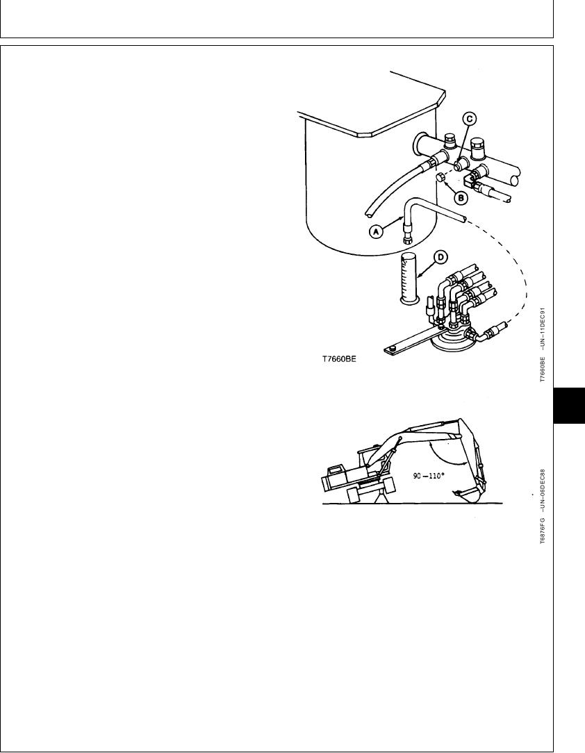
5. Disconnect the drain line (A) at return manifold. Put
line in a calibrated container (D). Install a cap (B) on
the open fitting (C).
6. Raise track off the ground for side being checked.
7. Run machine at specifications.
Engine in Standard Mode--Specification
Speed ........................................................................................... Fast Idle
Work Mode Selector--Specification
Position ........................................................................................ Dig Mode
E Mode Switch--Specification
Position .................................................................................................. Off
HP Mode Switch--Specification
Position .................................................................................................. Off
Auto-Idle Switch--Specification
Position .................................................................................................. Off
Propel Speed Switch--Specification
9025
Position ....................................................................... Slow Speed (Turtle)
25
135
8. For propel motor being checked, actuate propel
forward function at full speed for one minute. Record
amount of leakage. Repeat procedure for reverse.
If leakage is more than specification, repair or replace
motor.
Propel Motor--Specification
Leakage ................................................... 1.5--2.0 L/min (0.4--0.53 gpm)
new acceptable while propelling
with track raised
Leakage ........................................................... 3.4 L/min (0.80 gpm) used
A--Propel Motor Drain Line
maximum acceptable while
B--Cap
propelling with track raised
C--Fitting
D--Calibrated Container
If leakage is substantially more in one direction than the
other, a seal in the rotary manifold may be leaking. To
isolate leakage to the propel motor or rotary manifold,
check leakage at the propel motor.
Continued on next page
TX,9025,GG2667 1909MAY973/5
6-266