
TM 5-3805-280-24-1
Track System
01
REMOVE AND INSTALL TRACK CARRIER
0130
16
ROLLER
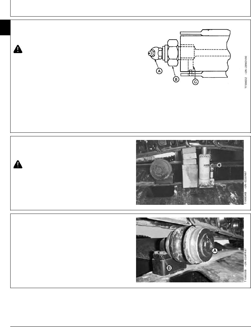
CAUTION: Prevent possible injury from high
pressure grease. Do not remove grease fitting
(A) from valve (B).
1. Loosen valve (B) one to two turns to release grease
through bleed hole (C).
A--Grease Fitting
B--Valve
C--Bleed Hole
TX,01,UU3842
1918SEP981/4
2. Raise track link, using a jack, enough to permit carrier
roller removal.
CAUTION: Prevent accidental lowering of track
by securely supporting track before attempting
service procedure.
3. Install wooden blocks between track link and frame.
TX,01,UU3842
1918SEP982/4
4. Remove cap screws (B) and carrier roller (A).
5. Repair or replace parts as necessary. (See following
procedure in this group.)
6. Install carrier roller and tighten cap screws (B).
Roller-to-Track Frame Cap Screw--Specification
Torque ......................................................................... 265 Nm (195 lb-ft)
Continued on next page
TX,01,UU3842
1918SEP983/4
11-16