
TM 5-3805-280-24-1
Hydraulic System
Item
Measurement
Specification
Stop-to-Frame Cap Screw
40 Nm (30 lb-ft)
Rotary Manifold
373 Nm (275 lb-ft) first rotation
02
237 Nm (175 lb-ft) second rotation
0260
170 Nm (125 lb-ft) third rotation
5
Cover-to-Housing Cap Screw
49 Nm (36 lb-ft)
CED,OUOE003,1158
1918SEP982/2
REMOVE AND INSTALL PROPEL MOTOR
AND BRAKE
1. Disconnect track. (See Remove Track Chain, Group
0130.)
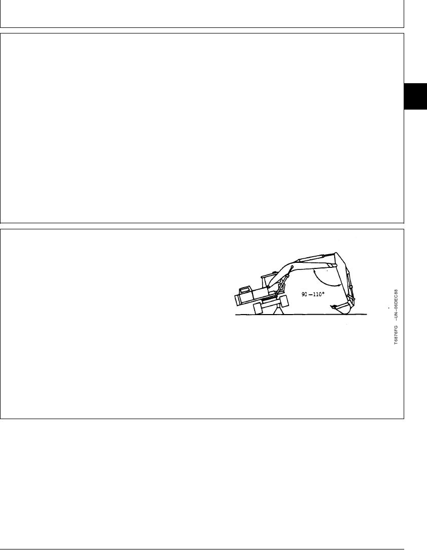
2. Swing upperstructure 90 and lower bucket to raise
track off ground. Keep angle between boom and arm
90--100 and position round side of bucket on ground.
Put a support stand under the carriage.
Continued on next page
TX,02,UU3722
1918SEP981/4
12-30