
TM 5-3805-280-24-2
Cylinder Head and Valves
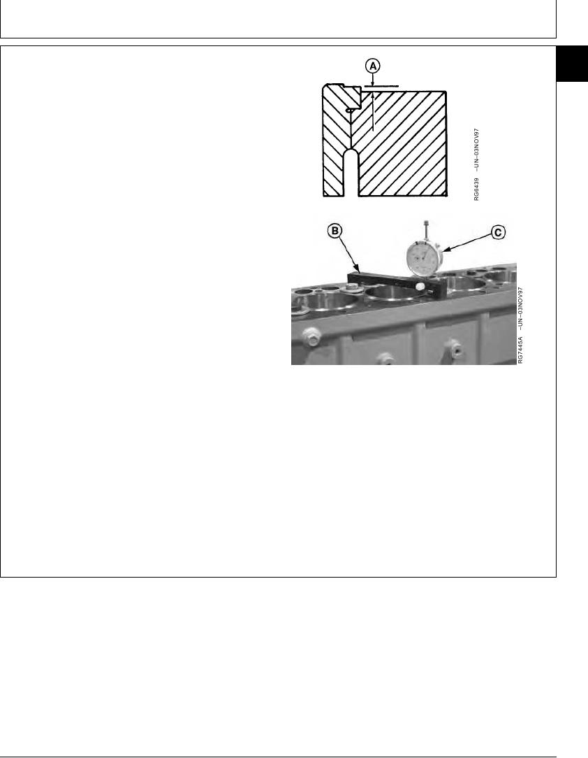
MEASURE CYLINDER LINER STANDOUT
05
45
(HEIGHT ABOVE BLOCK)
1. Secure liners using cap screws and flat washers. Flat
washers should be at least 3.18 mm (1/8 in.) thick.
Tighten cap screws to 68 Nm (50 lb-ft).
2. Using JDG451 or KJD10123 Gauge (B) and D17526CI
or D17527CI Dial Indicator (C), measure liner height
(A) at 1, 5, 7, and 11 o'clock positions as viewed from
flywheel end of engine. Record all measurements by
cylinder number.
Cylinder Liner Height Above Block--Specification
Height .................................................... 0.030--0.100 mm (0.001--0.004
in.)
Cylinder Liner Height Difference At Nearest Point of Two Adjacent
Liners, or Within a Single Liner--Specification
Maximum Permissible Height..................................... 0.05 mm (0.002 in.)
Difference
IMPORTANT: ONE LINER SHIM ONLY may be
installed under each liner flange.
A--Liner Height
3. Remove and shim, or replace, any liner that does not
B--Gauge
meet height specifications. (See Group 10.)
C--Dial Indicator
NOTE: Two sizes of shims are available: 0.05 mm (0.002
in.) and 0.10 mm (0.004 in.).
RG,05,DT7345 1911NOV971/1
13-103