
TM 5-3805-280-24-2
Camshaft, Balancer Shafts and Timing Gear Train
RG7708 UN07NOV97
16
2. Inspect thrust plate (A) for scoring or excessive wear.
37
Balancer Shaft Thrust Plate (New)--Specification
Thickness............................................. 2.97--3.02 mm (0.117--0.119 in.)
A--Thrust Plate
RG,16,DT7488 1914NOV972/2
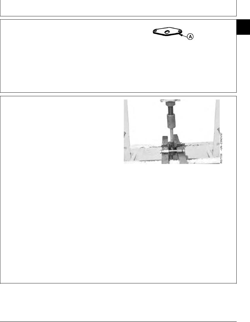
REMOVE AND INSTALL BALANCER SHAFT
IMPORTANT: DO NOT intermix gears and shafts.
Shafts are finish lapped in different
locations, therefore, balancer shafts
MUST BE installed in the location from
which removed. Reversing shaft
locations could result in excessive
bushing and shaft wear. If in doubt
about proper shaft locations, replace
the balancer shaft and bushings.
NOTE: Balancer shaft kits provided for service are
delivered without gear.
1. Support back side of gear in a press and push on
balancer shaft to remove gear.
2. Inspect woodruff key or spring pin (later engines), gear,
and thrust plate for cracks and wear. Replace if
necessary.
Continued on next page
RG,16,DT7487 1914NOV971/2
13-269