
TM 5-3805-280-24-2
Camshaft, Balancer Shafts and Timing Gear Train
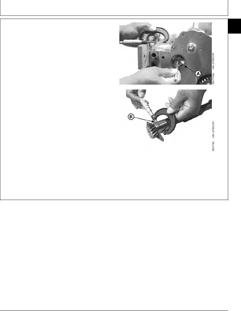
INSPECT AND MEASURE BALANCER SHAFT
16
35
BUSHINGS AND JOURNALS
1. Inspect, measure and record bushing ID (A) at all
locations.
2. Measure balancer shaft journal OD (B). Difference
between journal OD and bushing ID is oil clearance.
If oil clearance is not within specification, install new
bushings and, if necessary, new balancer shaft.
Balancer Shaft Bushing (New)--Specification
ID ............................................................................... 40.177--40.237 mm
(1.5818--1.5841 in.)
Balancer Shaft Journal--Specification
OD ............................................................................. 40.135--40.161 mm
(1.5801--1.5811 in.)
Balancer Shaft Journal-to-Bushing--Specification
Oil Clearance................................................................. 0.016--0.102 mm
(0.0006--0.0040 in.)
Cylinder Block Bore ID for Balancer Shaft Bushing--Specification
A--Bushing ID
B--Journal OD
ID ............................................................................... 43.262--43.288 mm
(1.7032--1.7042 in.)
RG,16,DT7490 1914NOV971/1
13-267