
TM 5-3805-280-24-2
Camshaft, Balancer Shafts and Timing Gear Train
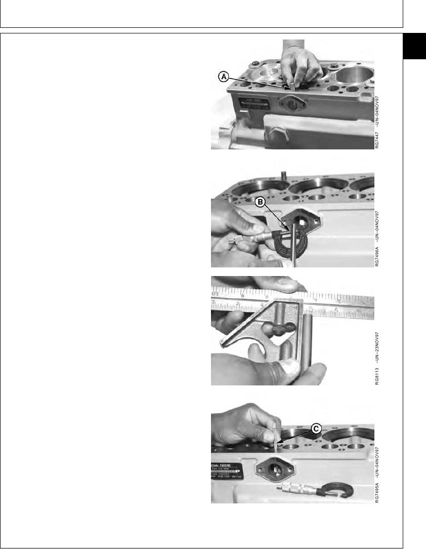
INSPECT, MEASURE, AND INSTALL FUEL
16
31
SUPPLY PUMP PUSH ROD
1. Remove and clean push rod (A). Label end(s) for
reassembly in same orientation.
2. Measure push rod OD (B). If OD is less than
specifications listed, install a new push rod.
Fuel Supply Pump Push Rod--Specification
OD ................................................................................. 9.891--9.917 mm
(0.3894--0.3904 in.)
3. Check crown on push rod ends. If flat or concave,
replace push rod and check camshaft lobe for wear.
(See Group 16).
4. Measure push rod bore ID (C) in block.
Fuel Supply Pump Push Rod Bore in Block--Specification
ID ................................................................................... 10.00--10.05 mm
(0.3937--0.3957 in.)
Repair or replace block as necessary.
5. Lubricate push rod with clean engine oil and install in
bore with same end orientation as removed.
A--Push Rod
B--Push Rod OD
C--Push Rod Bore ID
RG,16,DT7493 1914NOV971/1
13-263