
TM 5-3805-280-24-2
Cooling System
25
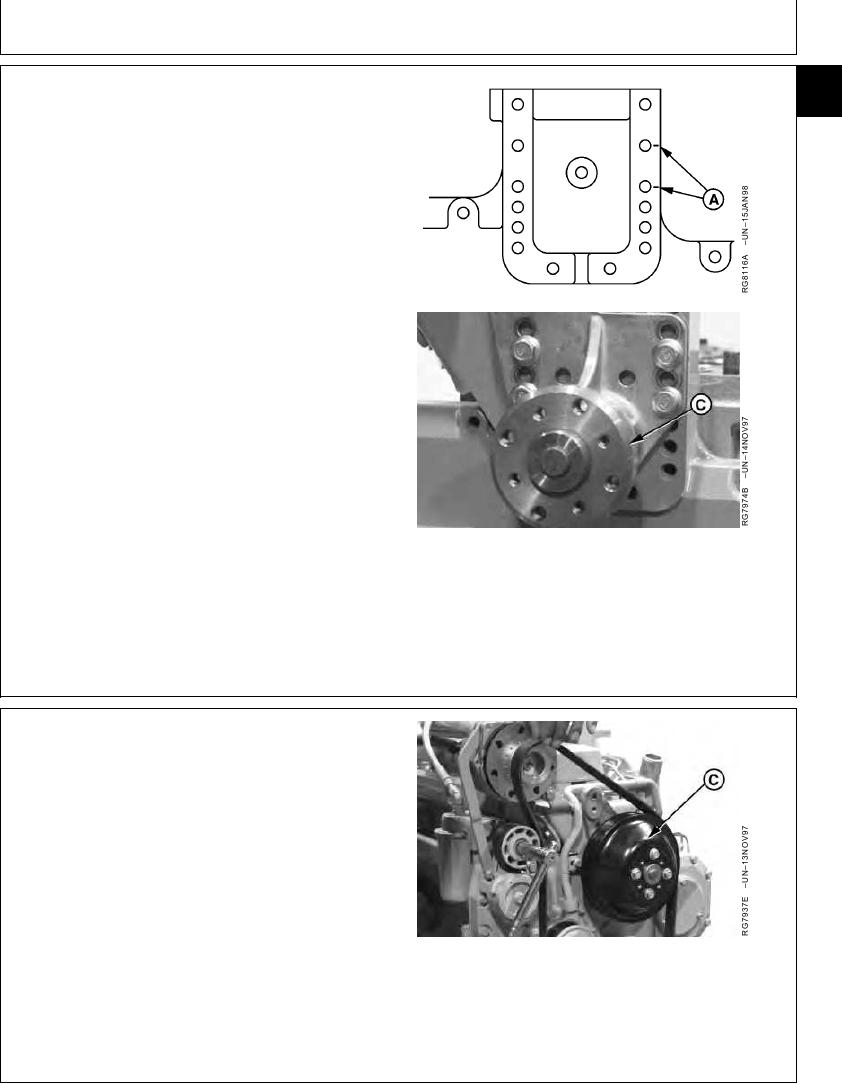
NOTE: Cap screw position A is used as an example only.
31
Position of fan drive varies by application.
2. Install hub (C) with fan drive assembly, in positions (A)
marked during disassembly, and tighten cap screws to
specifications.
Fan Drive Assembly-to-Timing Cover--Specification
Torque ............................................................................. 70 Nm (52 lb-ft)
A--Cap Screw Position
C--Fan Drive Hub
RG,25,JW7547
1920NOV972/3
3. Install fan pulley (C) and tighten cap screws to
specifications.
Fan Pulley-to-Pulley Hub M8 Cap Screws--Specification
Torque ............................................................................. 35 Nm (26 lb-ft)
Fan Pulley-to-Pulley Hub M10 Cap Screws--Specification
Torque ............................................................................. 70 Nm (52 lb-ft)
4. Install poly-vee belt. Be sure belt is correctly seated in
all pulley grooves.
C--Fan Pulley
RG,25,JW7547
1920NOV973/3
13-354