TM 5-3805-280-24-2
Cooling System
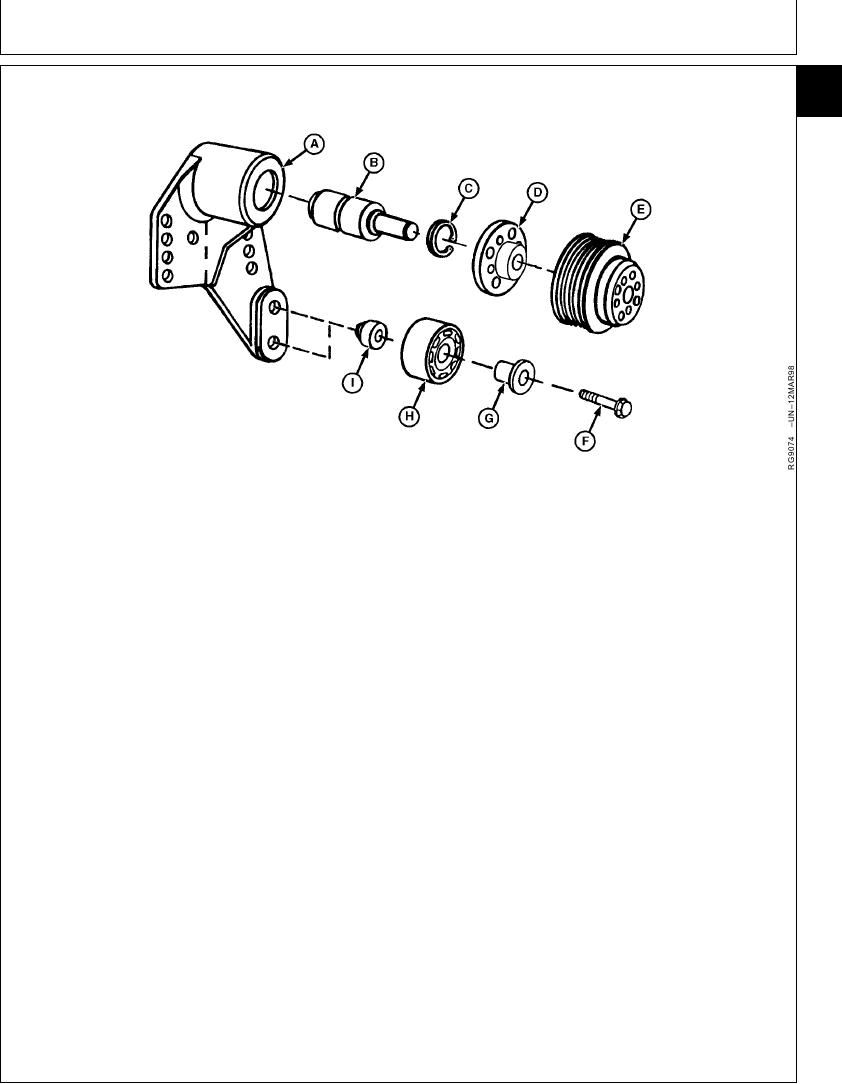
REPLACE BEARINGS IN ADJUSTABLE FAN DRIVE ASSEMBLY
25
27
A--Bearing Housing
D--Hub
G--Sleeve
B--Bearing/Shaft
E--Pulley
H--Idler Pulley
C--Snap Ring
F--Cap Screw
I--Spacer
Bearing Housing--Specification
DISASSEMBLE FAN DRIVE ASSEMBLY
ID ........................................................................ 38.018--38.038 mm
1. Support back side of fan hub (D) and press nose of
(1.4968--1.4976 in.)
bearing/shaft (B) out of hub.
Bearing--Specification
2. Remove snap ring (C) from front bore of bearing
OD....................................................................... 38.087--38.100 mm
housing (A).
(1.4995--1.5000 in.)
3. Support front nose of bearing housing and press
Shaft--Specification
bearing/shaft out of housing. Discard bearing.
OD....................................................................... 18.948--18.961 mm
4. Remove parts (F--I) if required.
(0.7460--0.7465 in.)
Hub--Specification
5. Thoroughly clean and inspect fan hub, bearing
housing and idler pulley for cracks or any other
ID ........................................................................ 18.910--18.936 mm
damage.
(0.7445--0.7455 in.)
6. On fan drive assemblies (option codes 2301 and
2302), measure parts and compare with
specifications given. Replace parts not within
specifications.
Continued on next page
RG,25,JW7548
1920NOV971/4
13-350

