
TM 5-3805-280-24-2
Cooling System
25
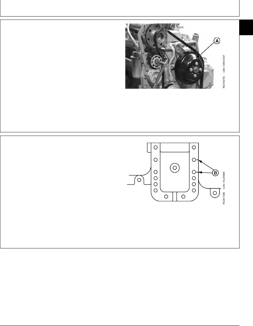
3. Remove fan pulley (A).
25
4. Inspect pulley and grooves
A--Fan Pulley
RG,25,JW7549
1920NOV972/4
NOTE: Cap screw position (B) is used as an example
only. Position of fan drive varies by application.
5. Mark cap screw positions (B) on timing gear cover
before removal to assure that fan pulley is installed in
same position as removed to assure proper belt
tension.
B--Fan Drive Mounting Position
Continued on next page
RG,25,JW7549
1920NOV973/4
13-348