
TM 5-3805-280-24-2
Hydraulic System
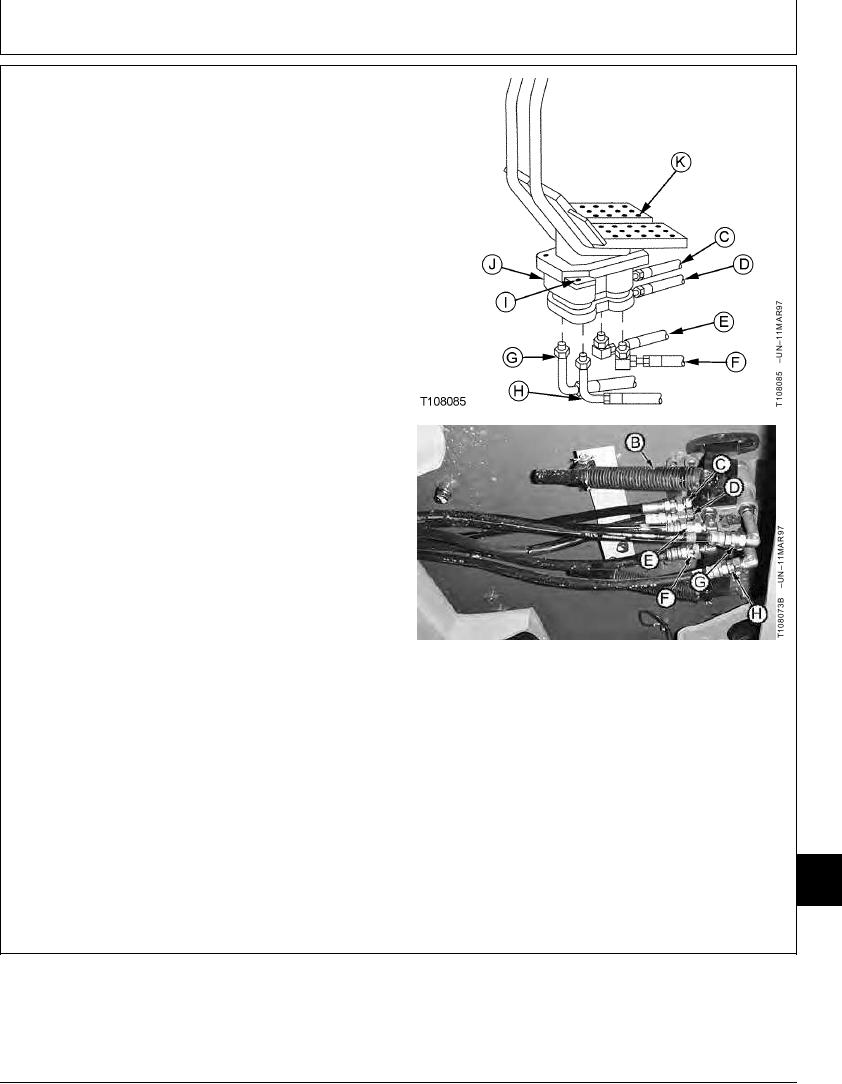
2. Disconnect lines (C--H). Install plugs and caps.
3. Remove cap screws to remove pedals (K), levers, and
damper brackets.
4. Remove cap screws (I) to remove propel pilot
controller (J).
5. Repair or replace parts as necessary.
6. Tighten valve mounting cap screws (I).
Controller-to-Cab Platform Cap Screw--Specification
Torque ............................................................................. 49 Nm (36 lb-ft)
7. Tighten pedal-to-lever cap screws.
Propel Pedal-to-Lever Cap Screw--Specification
Torque ............................................................................. 49 Nm (36 lb-ft)
8. After propel pilot controller is installed, check the
operation of all functions to be sure they operate
correctly.
B--Propel Pedal Dampener
C--To Pilot Shut-Off Valve
D--From Pilot Shut-Off Valve
E--To Right Propel Reverse Top Pilot Cap
F--To Left Propel Reverse Top Pilot Cap
G--To Right Propel Forward Bottom Pilot Cap
H--To Left Propel Forward Bottom Pilot Cap
I--Cap Screw (2 used)
J--Propel Pilot Controller
K--Pedal, Lever and Bracket
33
3360
77
TX,33,GG2557 1921SEP982/2
21-113