
TM 5-3805-280-24-2
Mechanical Drive Elements
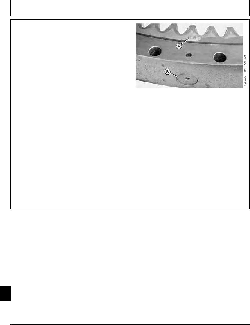
IMPORTANT: The tooth marked with the letter "G" or
"S" or equivalent is the starting and
stopping point for the hardening
process. The tooth and the bearing
loading plug must be installed on the
right side of the machine so the use of
that part of the swing bearing is
minimized.
6. Install swing bearing on undercarriage so the tooth (A)
marked "G" or "S" or equivalent and bearing loading
plug (B) is to the right side of machine.
A--Tooth
7. Install cap screws and lock washer. Tighten cap
B--Loading Plug
screws.
Undercarriage-to-Swing Bearing Cap Screw--Specification
Torque ......................................................................... 740 Nm (540 lb-ft)
8. Apply multi-purpose EP grease to swing bearing teeth
and pinion shaft. (See Track Adjuster, Working Tool
Pivot, Swing Bearing, and Swing Bearing Gear Grease
in Group 0004.)
TX,43,UU4005
1923SEP982/2
43
4350
30
22-29