TM 5-3805-281-24-1
Adjustments
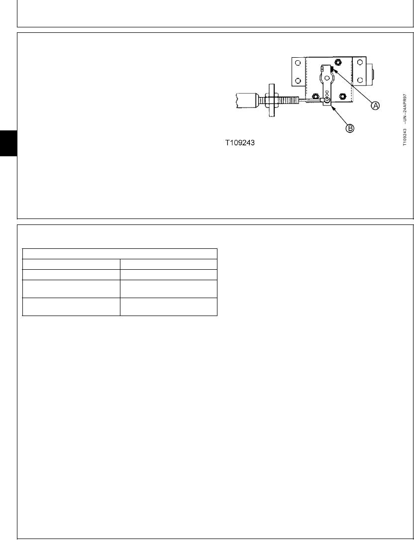
4. Check that engine speed control cable is connected to
the outer hole of engine control motor arm (B).
5. Loosen cap screw (A) in arm (B).
6. Adjust the arm on the shaft so injection pump lever just
contacts the external slow idle stop.
7. Tighten cap screw (A).
Arm-to-Engine Control Motor Shaft Cap Screw--Specification
9010
20
Torque .......................................................................... 13 Nm (115 lb-in.)
10
A--Cap Screw
8. Do the Engine Speed Learning Procedure. (See
B--Arm
procedure in this group.)
CED,TX08227,3183
1906JUN983/3
ENGINE SPEED LEARNING PROCEDURE
SPECIFICATIONS
Engine Slow Idle Speed
1050 + 100 - 0 rpm
1200 100 rpm
Engine Auto-Idle Speed
1900 100 rpm
Engine E (Economy) Mode
Speed
2050 75 rpm
Engine Fast Idle in Standard
Mode Speed
When the following components are repaired or replaced,
or when engine speeds deviate from specification, the
engine control motor adjustment and engine learning
control procedure must be performed.
Engine
Engine speed control cable
Engine control motor and sensor
Engine and pump controller
Fast and slow idle stop brackets
1. Stop the engine.
2. Disconnect the laptop computer from the diagnostic
test port.
3. Wait for 5 seconds.
Continued on next page
CED,TX08227,3184
1906JUN981/2

