TM 5-3805-281-24-1
Sub-System Diagnostics
process of rectification. The regulator (K) measures the
NORMAL OPERATION
B+ voltage (H) and compares it to an internal
reference. When the B+ voltage (H) starts to rise
The alternating current induced in the stator winding
above the reference voltage, the regulator (K) switches
(E) is rectified by the positive and negative diodes (F
off the field current. When the B voltage (H) starts to
and C) and delivered to the battery and current
fall below the reference voltage the regulator (K)
consuming accessories. The currents in the stator
switches on the field current. The regulator (K)
winding (E) are constantly changing magnitude and
switches the field on and off several thousand times a
direction. However, current flowing to the battery and
second in response to the current load placed on the
accessories always maintains the same direction. This
alternator output and the engine RPM.
is because no matter what position the rotor (M) is in,
all the diodes are simultaneously involved in the
9015
15
11
CED,OUOE012,13 1927OCT982/2
1 CHARGING CIRCUIT DIAGNOSTIC PROCEDURES
IMPORTANT: Do not disconnect electrical connectors while the engine is running. Damage to Engine and
Pump Controller or other components may result. Disconnect connectors only when instructed during a
test or check.
NOTE: For a problem that cannot be identified using the diagnostic procedures, check the wiring harnesses and
diodes in the circuits for shorts and opens.
1/1
ALTERNATOR (G3)
Key switch OFF.
YES: Alternator is OK.
OUTPUT CHECK
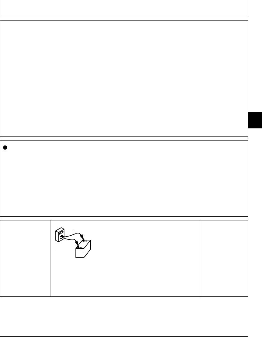
With voltmeter connected from battery (+) terminal to
NO: Repair alternator.
vehicle ground, measure and record battery voltage. 24 -
25.5 volts is normal.
Start and run engine at 1500 rpm, and check battery
voltage.
T6569AZ UN23AUG93
Does battery voltage increase to 27.4 - 28.4 volts?
1/1

