
TM 5-3805-281-24-1
Sub-System Diagnostics
ENGINE CONTROL (EC)
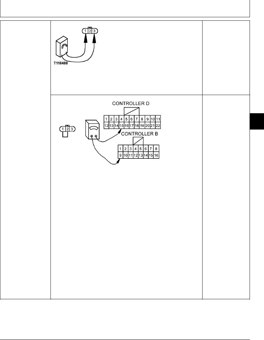
1--Positive Pin
YES: Go to next step.
SENSOR (B17)
2--Sense Pin
HARNESS CHECK
3--Negative Pin
NO: Harness has failed.
Repair.
Turn key switch OFF.
Disconnect harness from EC sensor.
Turn key switch ON.
T118488 UN21NOV98
Measure voltage between pin 1 and pin 3 of EC sensor
harness connector.
Is 5 volts measured?
YES: Harness is OK.
NO: Harness has failed.
9015
Repair.
15
75
T118379 1930NOV98
1--Positive Pin
2--Sense Pin
3--Negative Pin
Turn key switch OFF.
Disconnect harness from EC sensor.
Connect jumper wire between sensor harness connector pins 1 and 2.
Disconnect 22-pin connector D and 16-pin connector B from engine and pump
controller.
Measure continuity between pin 9 of connector B and pin 15 of connector D.
Is continuity measured?
1/1
4-143