
TM 5-3805-281-24-1
Sub-System Diagnostics
YES: Harness wire is OK.
MODE 1 OUTPUT TO
Go to next check.
ENGINE AND PUMP
CONTROLLER HARNESS
CHECK
NO: Harness wire is
open. Repair.
9015
15
T118395 1930NOV98
78
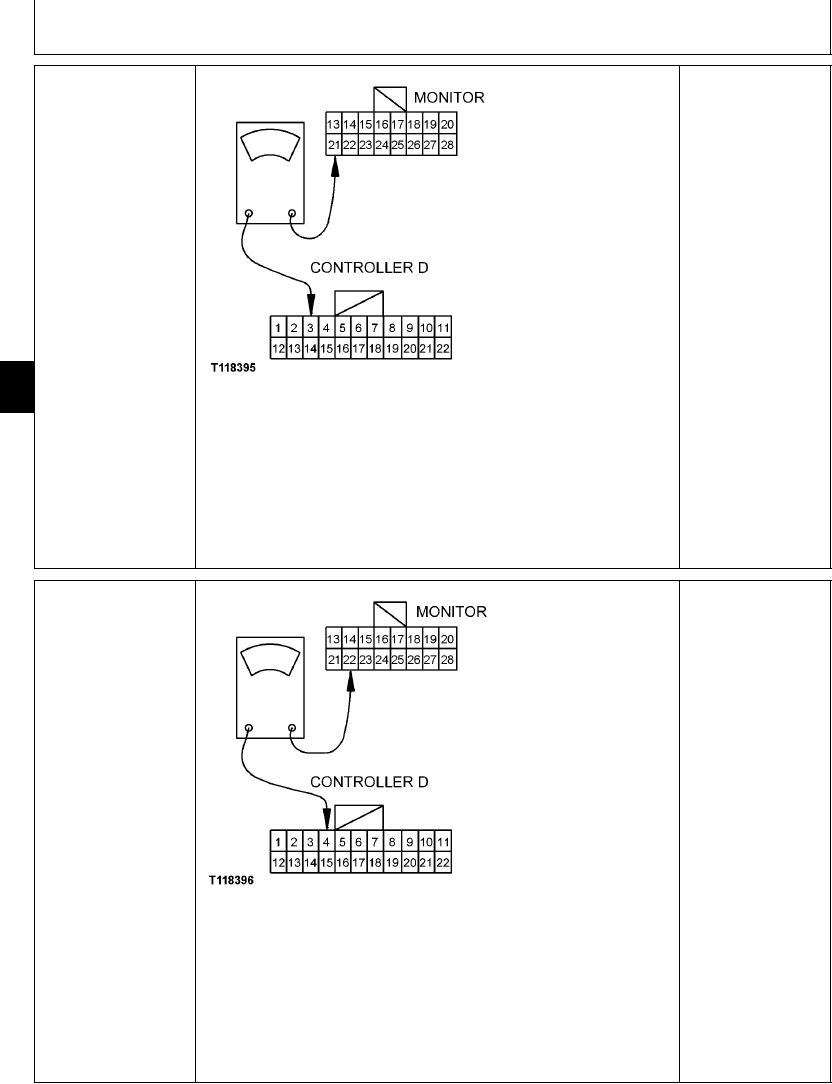
Disconnect 16-pin harness connector from monitor controller and display, and 22-pin
harness connector D from engine and pump controller.
Measure continuity between pin 21 of monitor controller harness connector and pin 3
of engine and pump controller harness connector D.
Is continuity measured?
1/1
MODE 2 OUTPUT TO
YES: Harness wire is OK.
ENGINE AND PUMP
CONTROLLER HARNESS
NO: Harness wire is
CHECK
open. Repair.
T118396 1930NOV98
Disconnect 16-pin harness connector from monitor controller and display, and 22-pin
harness connector D from engine and pump controller.
Measure continuity between pin 22 of monitor controller harness connector and pin 4
of engine and pump controller harness connector D.
Is continuity measured?
1/1
4-146