
TM 5-3805-281-24-1
Sub-System Diagnostics
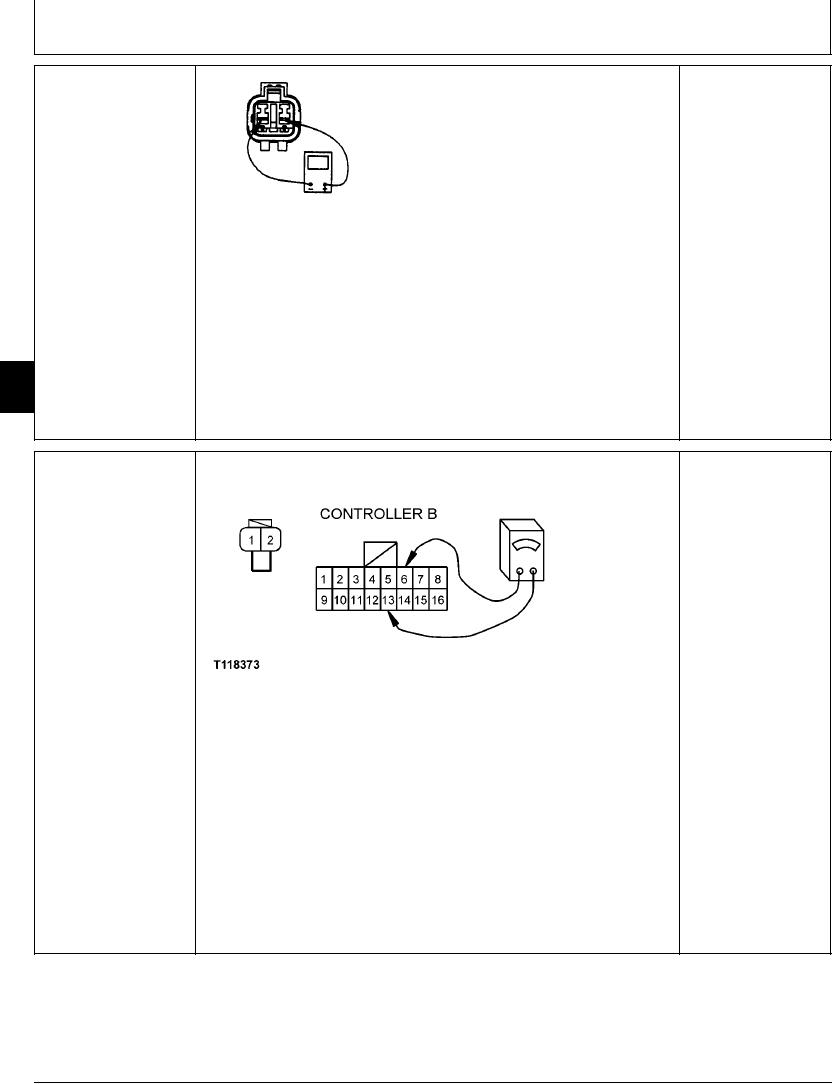
ENGINE SPEED (N)
Turn key switch OFF.
YES: Sensor is OK. Go
SENSOR (B16) CHECK
to next check.
Disconnect harness from engine speed sensor.
NO: Sensor has failed.
Measure resistance across speed sensor connector pins
Replace.
1 and 2.
Does ohmmeter read 810 240 ohms?
T7502BM
UN01APR91
Start engine.
Measure AC voltage at speed sensor terminals. Increase
engine speed.
Does AC voltage increase as engine speed increases?
9015
15
76
1/1
ENGINE SPEED (N)
YES: Harness is OK.
SENSOR (B16)
HARNESS CHECK
NO: Harness has failed.
Repair.
T118373 1930NOV98
Turn key switch OFF.
Disconnect harness from engine speed sensor.
Disconnect 16-pin connector B from engine and pump controller.
Measure continuity between pins 6 and 13 of connector B.
Does ohmmeter read open?
Connect jumper wire between sensor harness connector pins 1 and 2.
Is continuity measured?
1/1
4-144