
TM 5-3805-281-24-1
Tests
component of the engine speed control circuit has
After the electrical input signal are processed by the
been replaced or adjusted.
logic circuits, an electrical output signal is sent by the
controller to control engine speed by the engine control
The laptop computer, with the excavator diagnostics
motor (19--23), the control valve by the power boost
program loaded, is used to check and diagnose
(25) and arm regenerative (26) solenoid valves, and
problems with the switches and sensors through the
front and rear pumps by the speed sensing solenoid
diagnostic port (32). Also, engine speeds parameters
valve (24). The controller sends an electrical output
can be changed using Special Functions in Service
signal to the propel speed change solenoid valve (27)
Mode.
when all conditions are met to operate at fast speed
propel.
The learning switch (17) along with the learning control
(23) are used to learn the slow idle position when a
CED,TX08227,3020
1917MAR982/2
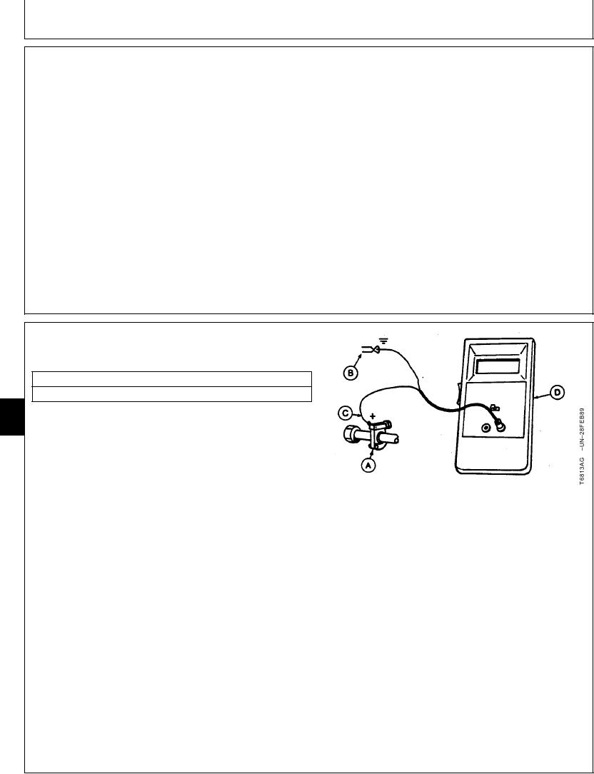
JT05801 CLAMP-ON ELECTRONIC
TACHOMETER INSTALLATION
SERVICE EQUIPMENT AND TOOLS
JT05801 Clamp-On Electronic Tachometer
9025
25
1. Before installing clamp-on electronic tachometer,
32
remove the paint from a straight section of injection
line within 100 mm (4 in.) of No. 1 injection nozzle.
Use emery cloth to remove the paint.
2. Install the clamp-on transducer (A). Tighten finger tight
only--DO NOT overtighten.
A--Clamp-On Transducer
B--Black Clip (-)
3. Connect the red clip (+) (C) to the clamp-on
C--Red Clip (+)
transducer.
D--Digital Readout Unit
4. Connect the black clip (-) (B) to a ground connection
such as the head of a cap screw or other metal part on
engine.
5. Start the engine. Check for a reading on the digital
readout unit (D).
CED,TX08227,2879
1911NOV971/1