
TM 5-3805-281-24-1
Tests
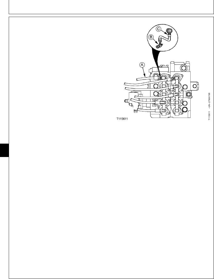
3. Disconnect a pilot line (A) at pilot cap fitting. Install tee
(B) and male quick coupler. Install the digital pressure
and temperature analyzer, and transducer, or a gauge
(C) .
4. Install the temperature probe on the hydraulic
tank-to-pump suction line. (See JT05800 Digital
Thermometer Installation in this group.)
5. Heat hydraulic oil to the specified temperature. (See
Hydraulic System Warm-Up Procedure in this group.)
Hydraulic Oil--Specification
Temperature ........................................................... 50 5C (120 10F)
6. Start and run engine at specification.
Engine--Specification
Speed ....................................................................... Slow Idle to Fast Idle
Work Mode Selector--Specification
A--Pilot Line
Position ........................................................................................ Dig Mode
B--203836 Tee
C--Gauge 7 000 kPa (70 bar) (1 000 psi)
E Mode Switch--Specification
Position .................................................................................................. Off
9025
25
HP Mode Switch--Specification
72
Position .................................................................................................. Off
Auto-Idle Switch--Specification
Position .................................................................................................. Off
NOTE: Spool actuation pressure is checked for each
function by installing the tee and gauge in that
pilot line and then actuating that function.
7. Actuate the function being checked to full stroke.
If valve spool actuation pressure is not to specification,
check pilot system pressure. (See Pilot Pressure
Regulating Valve Test and Adjustment in this group.
Continued on next page
TX,9025,GG2483
1921NOV973/4
6-219