
TM 5-3805-281-24-1
Tests
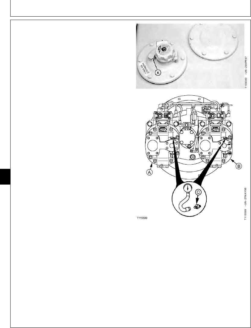
If laptop computer is not available, use the digital
pressure and temperature analyzer, and transducers,
or gauges.
a. Stop the engine.
b. Loosen vent plug (K) to release the air pressure in
hydraulic oil tank.
c. Install adapter (C) and male quick coupler to test
port on front pump (B) or rear pump (A). Connect
the analyzer and transducers or gauges.
3. Raise and lower boom to pressurize hydraulic oil tank.
4. Heat hydraulic oil to the specified temperature. (See
Hydraulic System Warm-Up Procedure in this group.)
Hydraulic Oil--Specification
Temperature ........................................................... 50 5C (120 10F)
5. Run machine at specification.
Engine--Specification
Speed ........................................................................................... Fast Idle
9025
Work Mode Selector--Specification
25
76
Position ........................................................................................ Dig Mode
E Mode Switch--Specification
Position .................................................................................................. Off
HP Mode Switch--Specification
Position .................................................................................................. Off
A--Rear Pump
Auto-Idle Switch--Specification
B--Front Pump
C--TH108328 Adapter (2 used)
Position .................................................................................................. Off
K--Vent Plug
6. Actuate the arm in function over relief.
Record the pressure reading for system relief valve.
7. Actuate the arm in function over relief and then push
the power boost button on the right control lever.
Continued on next page
CED,TX08227,3033
1918MAR983/5
6-223