
TM 5-3805-281-24-1
Tests
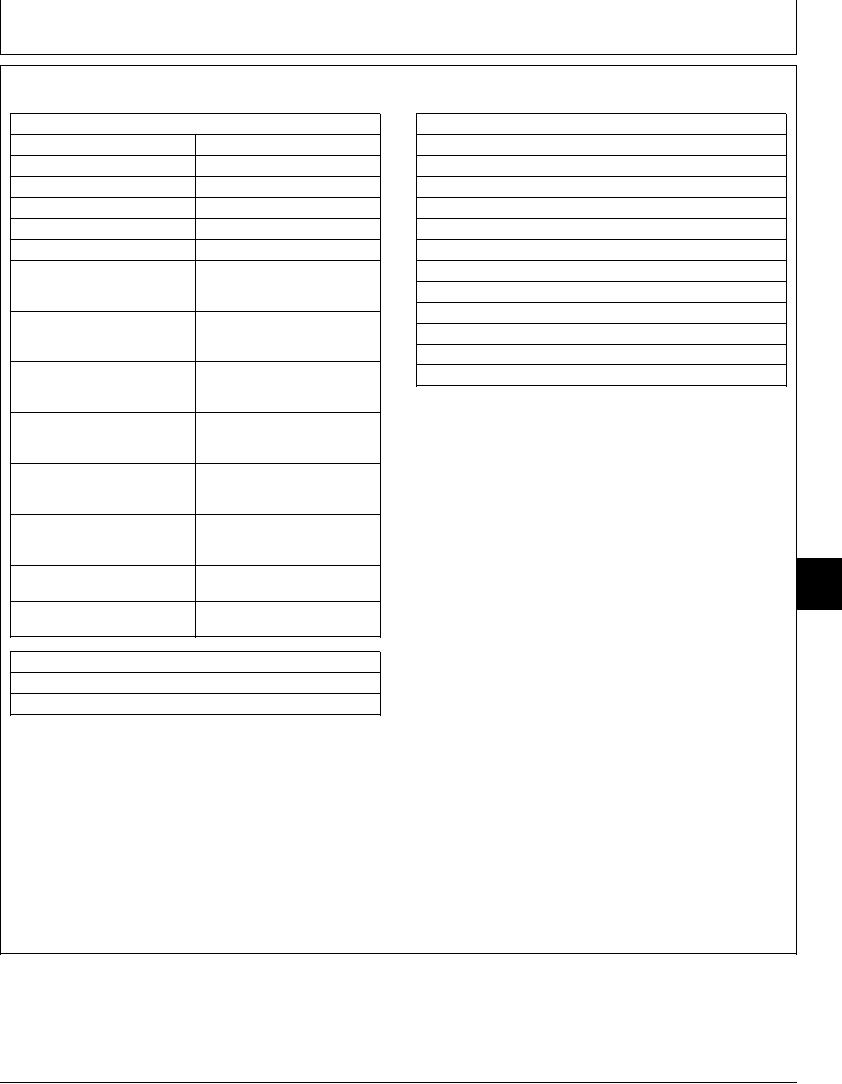
CIRCUIT RELIEF VALVE TEST AND ADJUSTMENT
SPECIFICATIONS
SERVICE EQUIPMENT AND TOOLS
50 5C (120 10F)
Hydraulic Oil Temperature
JT05801 Clamp-On Electronic Tachometer
Engine Speed
1200 rpm approximate
JT05800 Digital Thermometer
Work Mode Selector Position
Dig Mode
JT07290 Laptop Computer
E Mode Switch Position
Off
JT07274F Excavator Diagnostics Program Disk
HP Mode Switch Position
Off
JT07273 Cable
Auto-Idle Switch Position
Off
JT02156A Digital Pressure and Temperature Analyzer
Boom Up (Head End) and
33 345 + 980 - 0 kPa (333.4 +
JT02160 Transducer 70 000 kPa (700 bar) (10 000 psi)
Down (Rod End) Circuit Relief
9.8 - 0 bar) (4 835 + 140 - 0
Gauge 70 000 kPa (700 bar) (10 000 psi)
Valves Pressure
psi)
32 mm Combination Wrench
Bucket Dump (Rod End) Circuit
35 305 + 980 - 0 kPa (353.1 +
19 mm Combination Wrench
Relief Valve Pressure
9.8 - 0 bar) (5 120 + 140 - 0
psi)
17 mm Combination Wrench
Bucket Load (Head End) Circuit
33 345 + 980 - 0 kPa (333.4 +
6 mm Hex Key Wrench
Relief Valve Pressure
9.8 - 0 bar) (4 835 + 140 - 0
psi)
The purpose of circuit relief valves is to relieve high
Arm In (Head End) Circuit
33 345 + 980 - 0 kPa (333.4 +
pressure spike caused by external forces when
Relief Valve Pressure
9.8 - 0 bar) (4 835 + 140 - 0
functions are in neutral. The valves are checked and
psi)
adjusted to specification to protect components from
Arm Out (Rod End) Circuit
35 305 + 980 - 0 kPa (353.1 +
damage.
Relief Valve Pressure
9.8 - 0 bar) (5 120 + 140 - 0
psi)
1. Install a tachometer. (See JT05801 Clamp-On
Per 1/4 Turn of Adjusting
4 415 kPa (44.1 bar) (640 psi)
Electronic Tachometer Installation in this group.)
Screw Approximate Change
Pressure
9025
2. Install the temperature probe on hydraulic
Adjusting Screw-to-Cartridge
29 Nm (22 lb-ft) (260 lb-in.)
25
Nut Torque
tank-to-pump suction line. (See JT05800 Digital
79
31 870 980 kPa (318.7 9.8
Thermometer Installation in this group.)
System Relief Valve Pressure
bar) (4 620 140 psi)
ESSENTIAL TOOLS
TH108328 Adapter (2 used)
XPD34BTX (1/8 x 7/16-20 F 37) Male Quick Coupler
Continued on next page
CED,TX08227,3035 1923MAR981/6