TM 5-3805-281-24-1
Tests
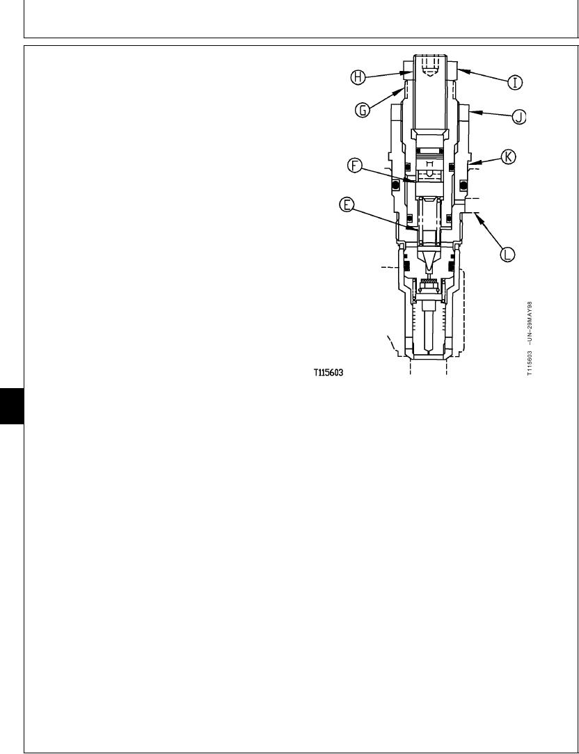
a. Loosen the 22 mm nut (I).
NOTE: The higher pressure setting for power boost must
be adjusted first and then the lower pressure
setting for the system relief valve. Turning the
adjusting screw (H) in pushes the piston (F) down
compressing the pilot poppet spring (E) increasing
the pressure setting to the power boost pressure
setting.
b. Turn the adjusting screw (H) in until piston (F) is
against bottom of bore in adjusting plug (G). Tighten
the nut just enough to hold the adjusting screw.
c. Loosen the 32 mm nut (J).
d. Turn adjusting plug (G) in to increase power boost
pressure; turn plug out to decrease power boost
pressure.
Per 1/4 Turn of Adjusting Plug Approximate
Change--Specification
Pressure .................................................... 4 415 kPa (44.1 bar) (640 psi)
e. Hold adjusting plug and then tighten 32 mm nut.
Adjusting Plug-to-Cartridge Nut--Specification
9025
E--Pilot Poppet Spring
25
F--Piston
Torque ........................................................... 29 Nm (22 lb-ft) (260 lb-in.)
78
G--Adjusting Plug
H--Adjusting Screw
f. Loosen the 22 mm nut.
I--22 mm Nut
J--32 mm Nut
K--System Relief and Power Boost Valve
g. Turn the adjusting screw out to decrease pressure
L--Power Boost Pilot Signal Passage
to get the specified system relief valve pressure.
Per 1/4 Turn of Adjusting Screw Approximate Change--
Specification
Pressure .................................................... 4 415 kPa (44.1 bar) (640 psi)
h. Hold adjusting screw and then tighten 22 mm nut.
Adjusting Screw-to-Adjusting Plug Nut--Specification
Torque ........................................................... 29 Nm (22 lb-ft) (260 lb-in.)
9. Check the pressure settings again.
CED,TX08227,3033
1918MAR985/5
6-225

