
TM 5-3805-281-24-1
Tests
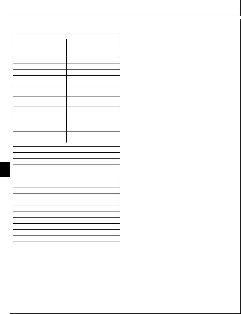
SYSTEM RELIEF AND POWER BOOST VALVE TEST AND ADJUSTMENT
SPECIFICATIONS
The system relief and power boost valve is used to
50 5C (120 10F)
limit the maximum pressure in the hydraulic system.
Hydraulic Oil Temperature
The purpose of test is to check and adjust system
Engine Speed
Fast Idle
relief and power boost valve to specification to protect
Work Mode Selector Position
Dig Mode
components from damage caused by excessive
E Mode Switch Position
Off
pressure. Power boost is actuated by pushing the
HP Mode Switch Position
Off
button on the right control lever or by actuating boom
Auto-Idle Switch Position
Off
up in precision work mode. Power boost is also
34 325 980 kPa (343.2 9.8
actuated when operating the propel function by the
Power Boost Pressure
bar) (4 980 140 psi)
pilot control signal from the propel pilot signal passage.
31 870 980 kPa (318.7 9.8
System Relief Valve Pressure
bar) (4 620 140 psi)
1. Install the temperature probe on the hydraulic
tank-to-pump suction line. (See JT05800 Digital
Per 1/4 Turn of Adjusting Plug
4 415 kPa (44.1 bar) (640 psi)
Approximate Change Pressure
Thermometer Installation in this group.)
Adjusting Plug-to-Cartridge Nut
29 Nm (22 lb-ft) (260 lb-in.)
Per 1/4 Turn of Adjusting
4 415 kPa (44.1 bar) (640 psi)
Screw Approximate Change
Pressure
Adjusting Screw-to-Adjusting
29 Nm (22 lb-ft) (260 lb-in.)
Plug Nut Torque
ESSENTIAL TOOLS
TH108328 Adapter (2 used)
XPD34BTX (1/8 x 7/16-20 F 37) Male Quick Coupler
9025
25
SERVICE EQUIPMENT AND TOOLS
74
JT05800 Digital Thermometer
JT07290 Laptop Computer
JT07274F Excavator Diagnostics Program Disk
JT07273 Cable
JT02156A Digital Pressure and Temperature Analyzer
JT02160 Transducer 70 000 kPa (700 bar) (10 000 psi)
70 000 kPa (700 bar) (10 000 psi) Gauge
22 mm Combination Wrench
6 mm Hex Key Wrench
32 mm Combination Wrench
19 mm Combination Wrench
Continued on next page
CED,TX08227,3033
1918MAR981/5