
TM 5-3805-281-24-1
Tests
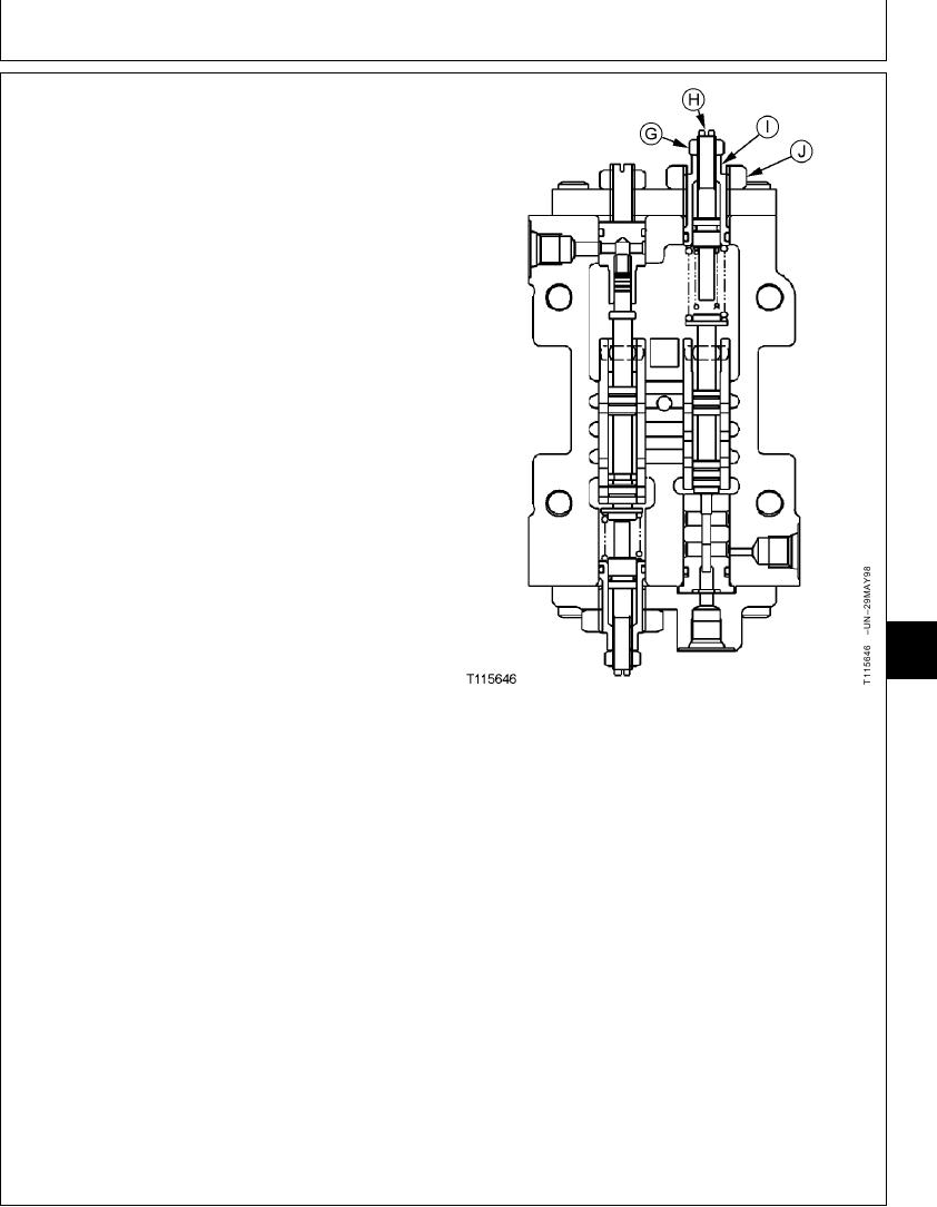
NOTE: The load adjusting screw (H) and load adjusting
cartridge (I) are located on the end of regulator
towards the engine.
c. Loosen 13 mm (G) on both regulators.
d. Turn load adjusting screws (H) out 1-1/2 turns.
Tighten 13 mm nuts.
e. Loosen large nuts (J) on both regulators.
f. Turn load adjusting cartridges (I) out 1-1/4 turns.
Leave nuts loose.
g. Run engine at fast idle.
h. Actuate and hold both propel functions over relief.
NOTE: Initial procedure is to adjust the load adjusting
cartridges (I) to match the two pumps before
making the final adjustment to get the combined
pump engine pulldown at medium pressure.
Hydraulic pressure increases as the load adjusting
cartridges are turned in because the pump flow is
increasing.
9025
i. Turn the load adjusting cartridge (I) on front pump
25
regulator in until engine speed just starts to
115
decrease. Then, slowly turn load adjusting cartridge
out and in to verify the exact point where engine
G--13 mm Nut
speed starts to decrease (0--5 rpm).
H--Load Adjusting Screw (Inner Spring) (Engine
Pulldown at High Pressure)
j. Turn the load adjusting cartridge (I) on rear pump
I--Load Adjusting Cartridge (Outer Spring)
regulator in until engine speed just starts to
(Engine Pulldown at Medium Pressure)
decrease. Then, slowly turn load adjusting cartridge
J--30 mm Nut
out and in to verify the exact point where engine
speed starts to decrease (0--5 rpm).
k. Release both propel functions.
NOTE: To avoid heating the oil excessively, only operate
the propel functions over relief to check the
pulldown after each adjustment of cartridge.
l. Turn both load adjusting cartridges (I) in equal
amounts. Start with 1/4 turn.
Continued on next page
CED,TX08227,3143
1928MAY987/13
6-262