
TM 5-3805-281-24-1
Tests
NOTE: Initial procedure is to adjust the load adjusting
screws (H) to match the two pumps before
making the final adjustment to get the combined
pump engine pulldown at high pressure.
d. Turn load adjusting screw (H) on front pump
regulator in until engine speed just starts to
decrease. Then, slowly turn load adjusting screw
out and in to verify the exact point where the engine
speed just starts to decrease (0--5 rpm).
e. Turn load adjusting screw (H) on rear pump
regulator in until engine speed just starts to
decrease. Then, slowly turn load adjusting screw
out and in to verify the exact point where the engine
speed just starts to decrease (0--5 rpm).
f. Release both propel functions.
NOTE: To avoid heating the oil excessively, only operate
the propel function over relief to check the
pulldown after each adjustment of screws
g. Turn both load adjusting screws in equal amounts.
Start with 1/4 turn.
h. Actuate and hold both propel functions over relief to
9025
check that combined pump engine pulldown speed
25
is to specification.
118
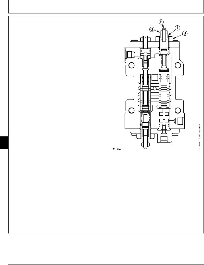
Load Adjusting Screw (Engine Pulldown at High Pressure)
(Inner Spring)--Combined Pump Engine
G--13 mm Nut
Pulldown--Specification
H--Load Adjusting Screw (Inner Spring) (Engine
Pulldown at High Pressure)
Speed ...................................................... 1950--2025 rpm at 24 132 kPa
I--Load Adjusting Cartridge (Outer Spring)
(241 bar) (3 500 psi) with tracks
(Engine Pulldown at Medium Pressure)
stalled
J--30 mm Nut
i. Hold the load adjusting screw and tighten 13 mm nut
(G) on both regulators.
Continued on next page
CED,TX08227,3143
1928MAY9810/13
6-265