
TM 5-3805-281-24-1
Hydraulic System
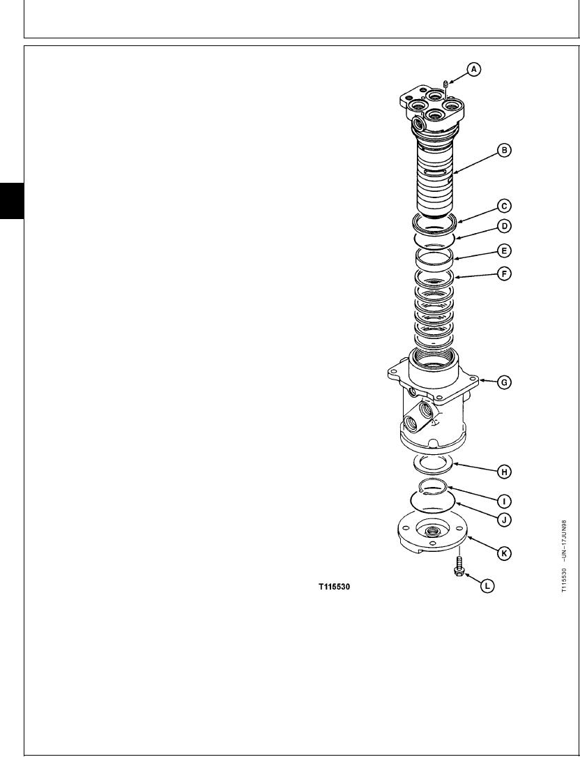
1. Make a mark on spindle (B), body (G) and cover (K) to
aid in assembly.
2. Remove cap screws (L) and cover (K). Inspect O-ring
(J) and replace if necessary.
3. Remove snap ring (I) and ring (H).
4. Carefully, remove spindle assembly (B--F) from
housing (G).
02
0260
5. Remove plug (A) in spindle to clean port. Install plug.
34
6. Remove O-ring (D), oil seal (C), oil seal rings (F) and
bushing (E).
7. Inspect and repair as necessary. Keep hydraulic oil on
all disassembled parts.
8. Install bushing (E), O-ring (D), oil seal rings (F) and oil
seal (C) in housing (G).
9. Install oil seal rings (F) on housing (G).
10. Install parts (B--F) in housing (G) so the mounting
holes for stop are towards the pointed indicator on
mounting flange and work port numbers are towards
the same side as housing.
11. Install ring (H) with chamfered side towards spindle.
Install snap ring (I) with flat side against ring (H).
12. Install O-ring (J) and cover (K) with nameplate on
cover (K) toward "L" mark on housing (G) mounting
flange. Install and tighten cap screws (L).
A--Plug
B--Spindle
C--Oil Seal
D--O-Ring
E--Bushing
F--Oil Seal Rings (6 used)
G--Housing
H--Ring
I--Snap Ring
J--O-Ring
K--Cover
L--Cap Screw (4 used)
Continued on next page
CED,OUOE023,181
1902JUN982/3
10-73