
TM 5-3805-281-24-1
Hydraulic System
CAUTION: To avoid injury from escaping fluid
under pressure, stop engine and relieve the
pressure in the system before disconnecting or
connecting hydraulic or other lines. Tighten all
connections before applying pressure.
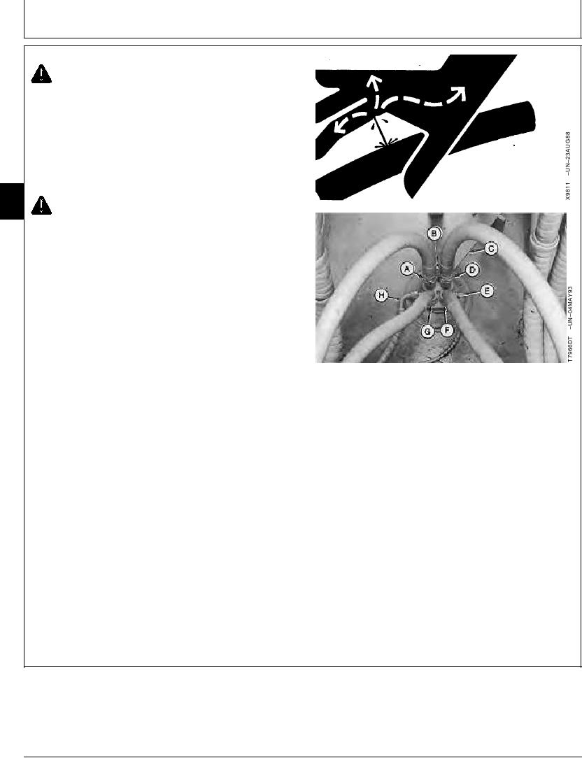
2. Disconnect lines (A and D--H).
3. Remove cap screws (B). Remove stop (C).
02
0260
CAUTION: The approximate weight of rotary
30
manifold is 27 kg (60 lb).
Rotary Manifold--Specification
Weight................................................................ 27 kg (60 lb) approximate
4. Attach the rotary manifold to a hoist using a lifting strap
and two rotary manifold lifting tools. (See Section 99
for instructions to make tools.)
A--Rotary Manifold Port 3-to-Left Propel Section
Bottom (Reverse) Port Line
B--Rotary Manifold Cap Screw (2 used)
C--Stop
D--Rotary Manifold Port 1-to-Right Propel Section
Bottom (Reverse) Port Line
E--Rotary Manifold P1 Port-to-Pilot Pressure
Regulating and Solenoid Valve Manifold "SA"
Port Line
F--Rotary Manifold Port 2-to-Right Propel Section
Top (Forward) Port Line
G--Rotary Manifold Port 4-to-Left Propel Section
Top (Forward) Port Line
H--Rotary Manifold D Port-to-Reservoir Port Line
Continued on next page
CED,OUOE023,179
1902JUN982/4
10-69