
TM 5-3805-281-24-1
Hydraulic System
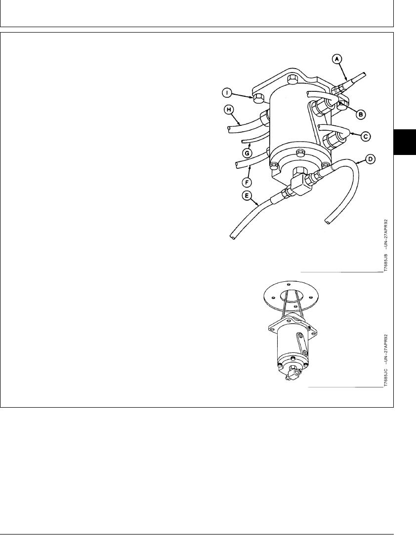
5. Disconnect lines (A--H).
6. Remove cap screws (I). Lower rotary manifold. Do not
damage rubber boot.
7. Replace parts as necessary.
8. Raise rotary manifold into position so that the letter R
on mounting flange and the work port number 1 and 2
are toward the right side of machine.
02
0260
9. Install cap screws (I) and tighten.
31
Manifold-to-Frame Cap Screw--Specification
Torque ............................................................................. 34 Nm (25 lb-ft)
10. Connect lines (A--H).
A--Rotary Manifold Port P1-to-Right Propel Speed
Change Port Line
B--Rotary Manifold Port 2-to-Right Propel Motor "AV"
(Forward) Port Line
C--Rotary Manifold Port Port 1-to-Right Propel Motor
"BV" (Reverse) Port Line
D--Rotary Manifold Bottom Tee Port-to-Right Propel
Motor Top Drain Port Line
E--Rotary Manifold Bottom Tee Port-to-Left Propel
Motor Top Drain Port Line
F--Rotary Manifold Port 3-to-Left Propel Motor "AV"
(Reverse) Port Line
G--Rotary Manifold Port P1-to-Left Propel Speed
Change Port Line
H--Rotary Manifold Port 4-to-Left Propel Motor "BV"
(Forward) Port Line
I--Cap Screw (4 used)
Continued on next page
CED,OUOE023,179
1902JUN983/4
10-70