
TM 5-3805-281-24-2
Removal and Installation
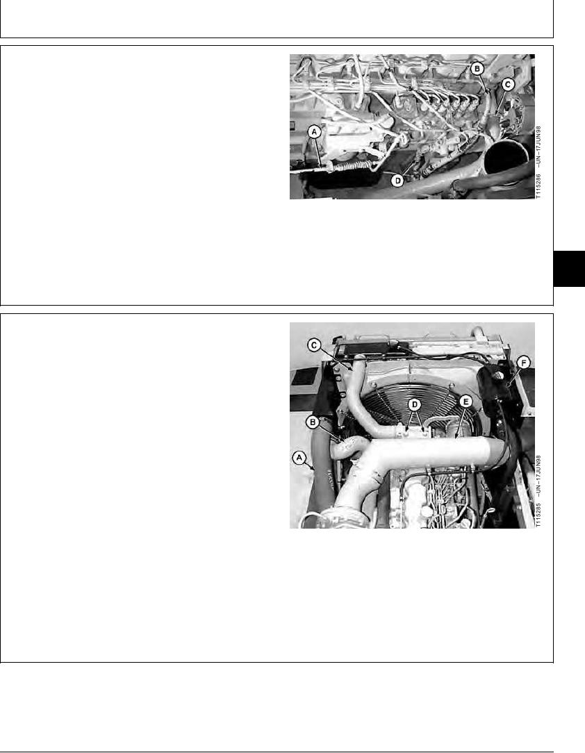
14. Install speed control cable (A). (See procedure in
Group 0515.)
15. Install water pump heater hose and engine block
heater hose.
16. Install lower radiator hose (C). Tighten clamp.
17. Install fuel supply line (D) and fuel return line (B).
Tighten clamps.
A--Speed Control Cable
B--Fuel Return Line
C--Lower Radiator Hose
D--Fuel Supply Line
04
0400
15
TX,0400,DH5397 1911NOV964/7
18. Install hoses (A--C). Tighten clamps.
19. Install air intake tube (E). Tighten clamps. Tighten cap
screws (D).
20. Install coolant expansion tank (F). (See procedure in
Group 0510.)
A--Charge Air Cooler-to-Turbocharger Hose
B--Charge Air Cooler-to-Intake Manifold Hose
C--Upper Radiator Hose
D--Cap Screw (2 used)
E--Air Intake Tube
F--Coolant Expansion Tank
Continued on next page
TX,0400,DH5397 1911NOV965/7
11-15