
TM 5-3805-281-24-2
Frame Installation
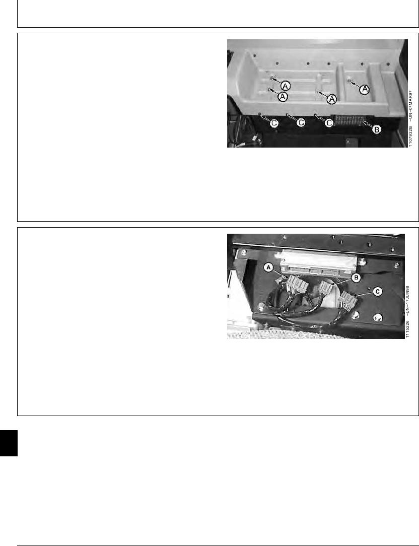
1. Inside the cab, remove four cap screws (A and C) and
the fuse box cover (B) to remove the rear console
cover.
2. Disconnect the battery ground and positive cables.
A--Cap Screw (4 used)
B--Fuse Box Cover
C--Cap Screw (3 used)
TX,16,UU3320
1907JUL982/3
3. Disconnect the engine and pump controller electrical
connectors.
After reconnecting batteries, engine speeds must be
recalibrated.
A--EPC Connector
B--EPC Connector
C--EPC Connector
TX,16,UU3320
1907JUL983/3
17
1740
2
16-2