
TM 5-3805-281-24-2
Removal and Installation
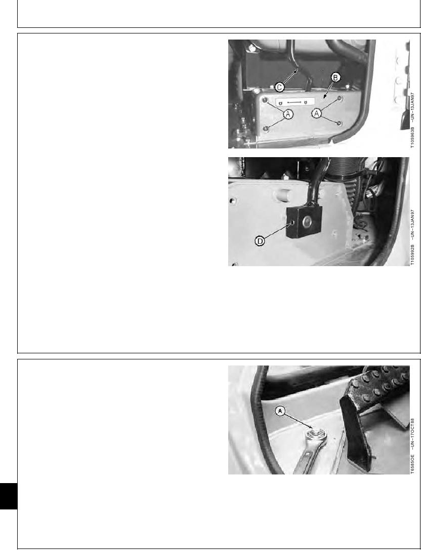
4. Remove screws (A) to remove cover (B).
5. Remove spring pin (D) to remove pilot shut-off lever
(C).
IMPORTANT: To avoid possible damage to switch
panel during assembly, be sure to mark
all corresponding bullet connector
wiring leads before disassembly.
Connecting bullet connectors to the
wrong wiring leads will damage
components in the switch panel.
6. Disconnect all main wire harness connectors, radio
speaker wires and radio antenna (if equipped),
windshield wiper motor, dome light and bullet
connectors as required.
7. Loosen and remove fresh air intake cowl cap screws
and remove cowl from inside rear wall of cab.
8. Disconnect windshield washer fluid tube from
windshield washer pump located in compartment
behind cab.
A--Screw (4 used)
B--Cover
C--Pilot Shut-Off Lever
D--Spring Pin
CED,OUOE027,244
1918MAY982/6
9. Remove lock nuts (A) and washers located at four
inside corners of cab.
10. Remove two cab-to-platform cap screws and washers
from each of four sides of cab.
18
A--Lock Nut
1800
2
Continued on next page
CED,OUOE027,244
1918MAY983/6
17-2