
TM 5-3805-281-24-2
Frames
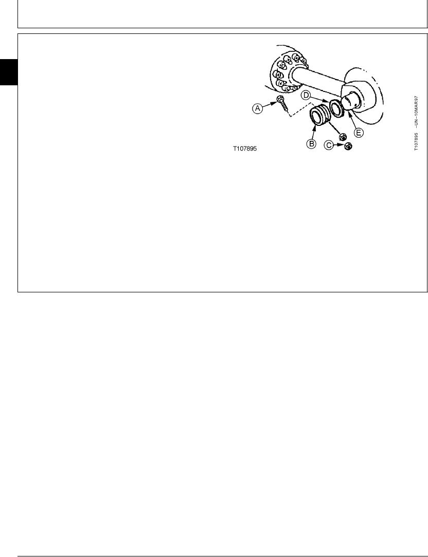
18. Install boom cylinders to boom.
33
Install shims (D) equally on each side to get minimum
3340
amount of clearance between boom and cylinder rod
16
end.
NOTE: There must be some clearance between boom
and cylinder rod end.
19. Tighten nuts (C) against each other, not the retainer.
Cap screw (A) must be free to turn in hole.
Boom Cylinder-to-Boom Pin M20 Cap Screw Nut--Specification
A--M20 Cap Screw (2 used)
Torque ..................................................... 540 Nm (400 lb-ft) tighten nuts
B--Retainer (2 used)
against each other, not the
C--M20 Nut (4 used)
retainer
D--Shim (Washer) (As Required)
E--Boom Cylinder-to-Boom Pin
20. Apply grease to all pivot joints. (See Track Adjuster,
Working Tool Pivot, Swing Bearing, and Swing
Bearing Gear Grease in Group 0004.)
CED,OUOE027,255
1918MAY987/7
19-34