TM 5-3805-281-24-2
Frames
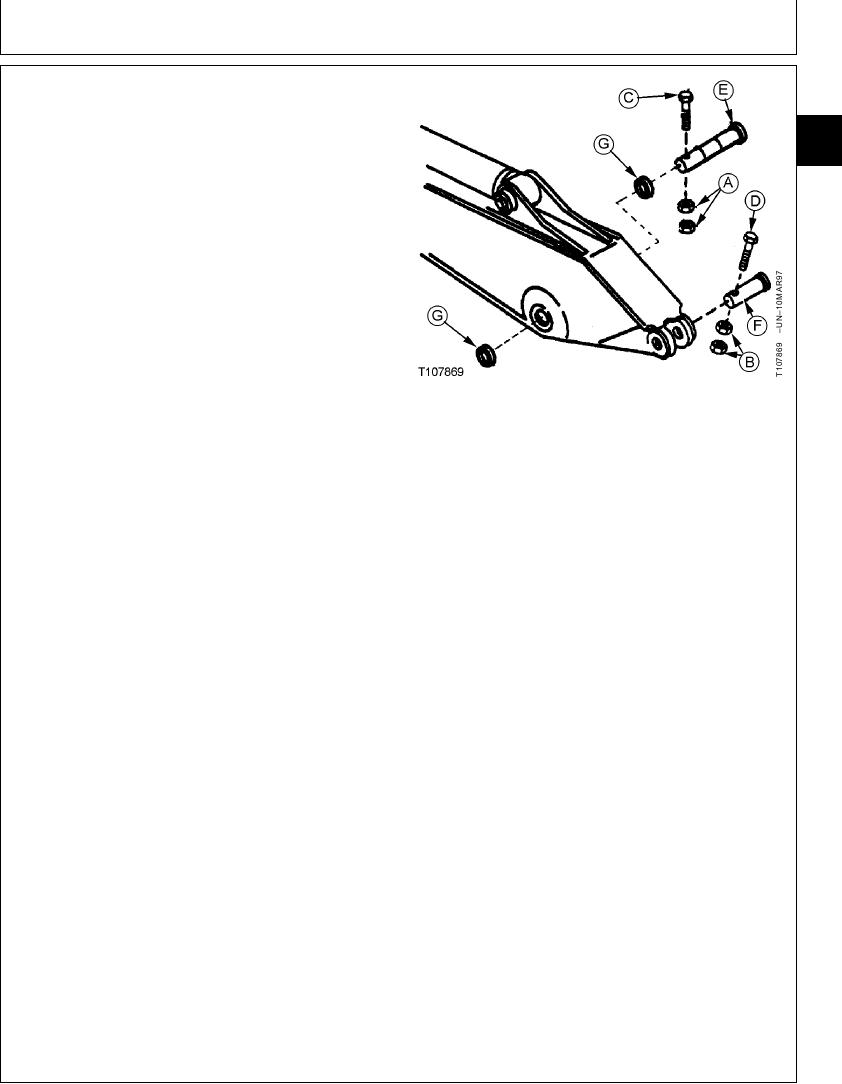
14. Install washers (G) equally on each side of arm to get
minimal amount of clearance at boom-to-arm joint.
33
3340
NOTE: There must be some clearance between boom
11
and arm.
15. Before installing pins (E and F), align pin bores so as
not to damage dust seal when pins are installed.
16. Tighten M20 nuts (A and B) against each other, not
the retainer. Cap screws (C) must be free to turn in
hole.
Boom-to-Arm Pin M20 Cap Screw Nut--Specification
Torque ..................................................... 540 Nm (400 lb-ft) tighten nuts
against each other, not the
retainer
A--M20 Nut (2 used)
Arm-to-Arm Cylinder Pin M20 Cap Screw Nut--Specification
B--M20 Nut (2 used)
C--M20 Cap Screw
Torque ..................................................... 540 Nm (400 lb-ft) tighten nuts
D--M20 Cap Screw
against each other, not the
E--Arm-to-Boom Pin
retainer
F--Arm-to-Arm Cylinder Pin
G--Washer (As Required)
17. For bucket cylinder, install washers equally on each
side of cylinder head and rod end to get minimal
amount of clearance in joints.
NOTE: There must be some clearance in joints.
18. Tighten M20 nuts against each other, not the retainer.
Cap screws (C) must be free to turn in hole
Bucket Cylinder Head End-to-Arm Pin M20 Cap Screw
Nut--Specification
Torque ..................................................... 540 Nm (400 lb-ft) tighten nuts
against each other, not the
retainer
Bucket Cylinder Rod End-to-Link M20 Cap Screw Nut--Specification
Torque ..................................................... 540 Nm (400 lb-ft) tighten nuts
against each other, not the
retainer
19. Apply grease to all pivot joints. (See Track Adjuster,
Working Tool Pivot, Swing Bearing, and Swing
Bearing Gear Grease in Fuels and Lubricants, Group
0004.)
CED,OUOE020,47 1913APR994/4
19-29

