
TM 5-3805-281-24-2
Frames
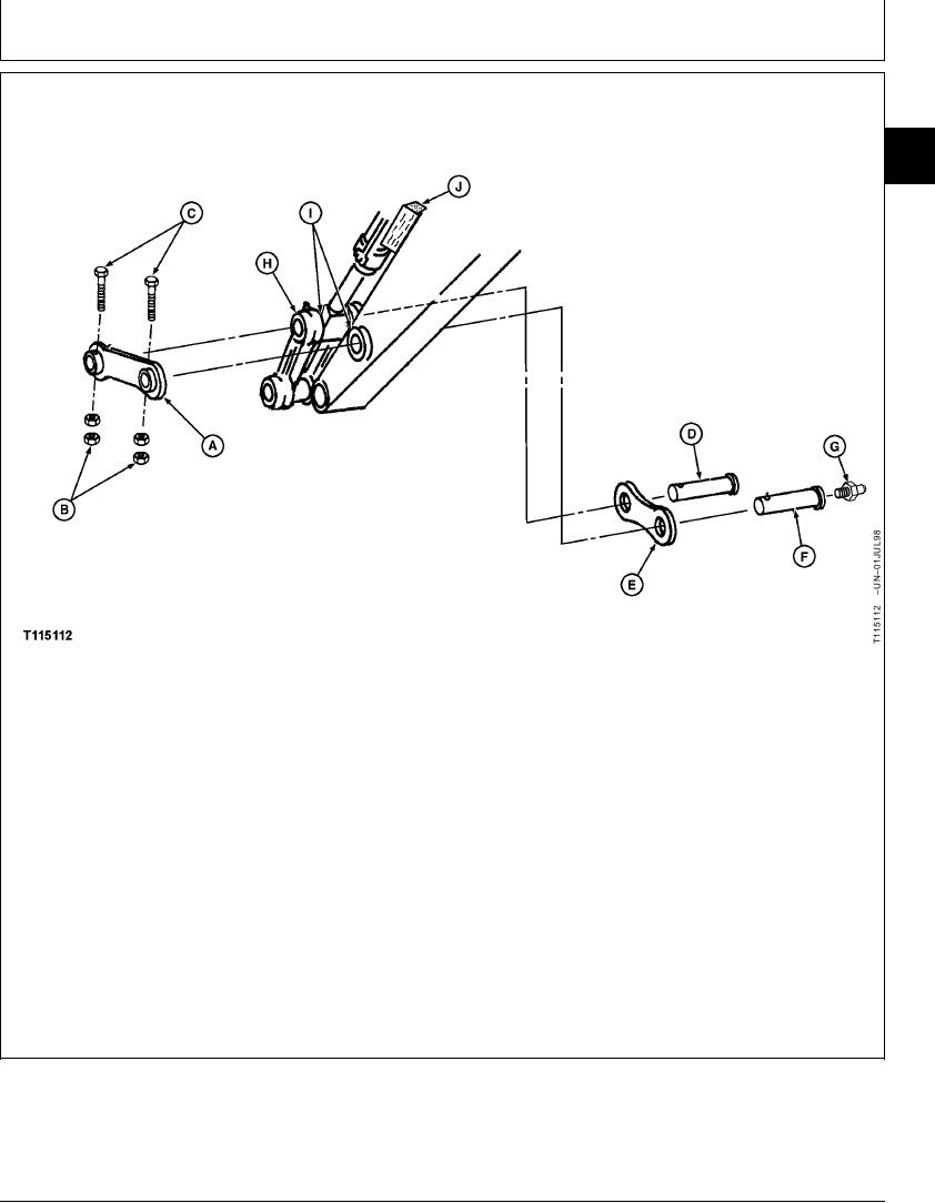
REMOVE AND INSTALL BUCKET LINKS
33
3340
7
A--Left Side Link
D--Links-to-Bucket
G--Lubrication Fitting (2
J--Wooden Block
B--M20 Nut (4 used)
Cylinder Pin
used)
C--M20 Cap Screw (2
E--Right Side Link
H--Center Link
used)
F--Links-to-Arm Pin
I--Washer (As Required)
NOTE: Removal of bucket is not necessary for the
cylinder and arm to hold cylinder up when
removal of just the bucket links. Remove the
links-to-bucket cylinder pin (D) is removed.
bucket if the arm is also being removed. (See
Remove and Install Bucket in Group 3302.)
2. Remove nuts (B) and cap screws (C).
As links-to-bucket cylinder pin (D) is removed, lower
1. Connect center link (H) to a hoist using a lifting
left (A) and right (E) side links to ground.
bracket. Put a wooden block (J) between bucket
Continued on next page
CED,OUOE027,253
1918MAY981/2