
TM 5-3805-281-24-2
Frames
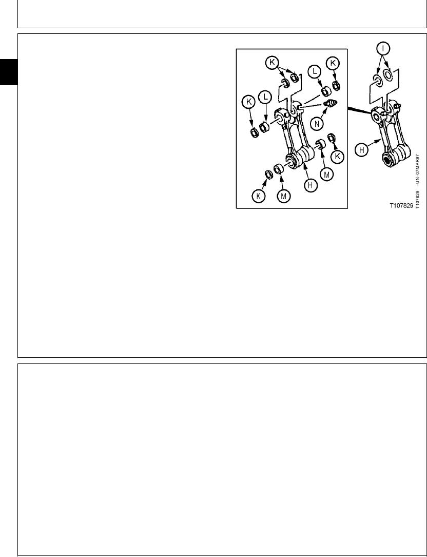
3. Inspect bushings (L and M) and dust seals (K). (See
Inspect Arm and Boom Pins and Bushings in this
33
group.)
3340
8
Replace parts as necessary.
4. Before installing pins, align pin bores so as not to
damage dust seal when pins are installed.
5. Tighten nuts (B) against each other, not the retainer.
Cap screw (C) must be free to turn in hole.
Pin-to-Retainer M20 Cap Screw Nut--Specification
Torque ..................................................... 540 Nm (400 lb-ft) tighten nuts
against each other, not the
retainer
6. Apply grease to pivot joints. (See Track Adjuster,
Working Tool Pivot, Swing Bearing, and Swing Bearing
Gear Grease in Fuels and Lubricants, Group 0004.)
H--Center Link
I--Washer (As Required)
J--Lubrication Fitting (2 used)
K--Dust Seal (6 used)
L--Bushing (2 used)
M--Bushing (2 used)
N--Lubrication Fitting (2 used)
CED,OUOE027,253
1918MAY982/2
REMOVE AND INSTALL ARM
1. Remove bucket. (See Remove and Install Bucket in
Group 3302.)
2. Retract arm cylinder.
3. Put a floor stand under end of boom so load is on
boom, not on arm cylinder.
4. Extend arm cylinder just enough to put end of arm on
ground.
5. Stop engine.
Continued on next page
CED,OUOE020,47 1913APR991/4